Mitsubishi Galant 9G. Manual - part 1586


  Index      Mitsubishi     Mitsubishi Galant 9G - service repair manual


Search            


Content   ..  1584  1585  1586  1587   ..


Mitsubishi Galant 9G. Manual - part 1586


MULTI-CENTER DISPLAY

TSB Revision

CHASSIS ELECTRICAL

54A-216

Precautions during service

.

Diagnosis tips concerning the entire sys-
tem

• Check that relevant wiring harness connectors 

are engaged correctly. If a failure is found, repair 
the connectors and check the trouble symptom 
again.

• If the wiring harness connectors are engaged 

correctly, check the wiring harness. If the wiring 
harness is in good condition, replace relevant 
components.

NOTE: If a system communication (CAN commu-
nication) related failure is suspected, diagnose 
the CAN communication system.

.

Diagnosis tips when only specific 
function(s) is defective

• Check that the wiring harness connectors related 

to the specific function are engaged correctly. If a 
failure is found, repair the connectors and check 
the trouble symptom again.

• If the wiring harness connectors are engaged 

correctly, check the wiring harness. If the wiring 
harness is in good condition, replace relevant 
components, which controls that function.

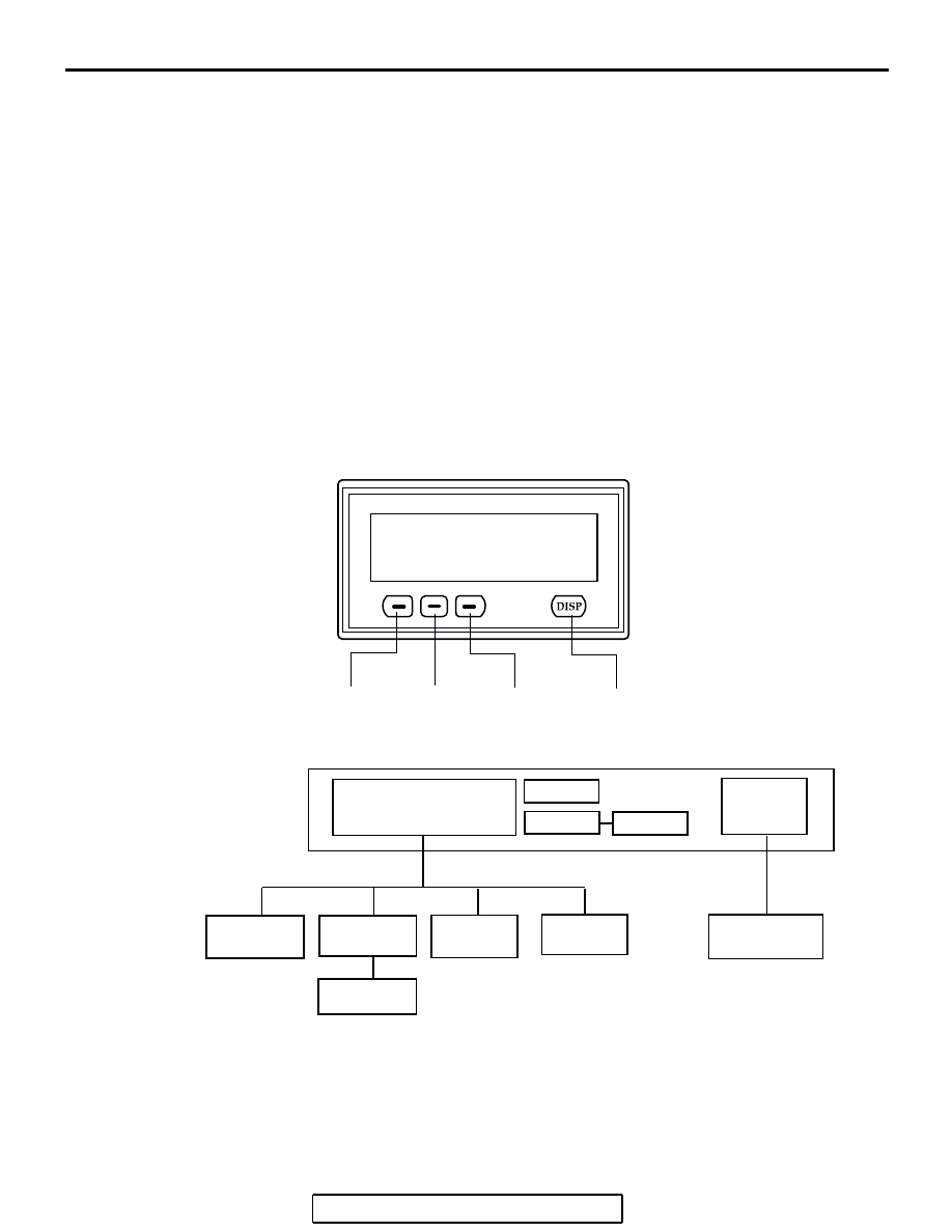
MULTI-CENTER DISPLAY SYSTEM <MIDDLE GRADE TYPE>

AC209281

FUNCTION 
BUTTON 
SWITCH 1

FUNCTION 
BUTTON 
SWITCH  2

FUNCTION 
BUTTON 
SWITCH  3

DISPLAY 
BUTTON 
SWITCH 

AB

MULTI-CENTER DISPLAY (middle grade type)

AC208668

A/C DISPLAY

AMBIENT  AIR TEPERATURE 
DISPLAY CUSTOMIZE FUNCTION

ETACS-ECU

A/C-ECU

POWER TRAIN 
CONTROL
MODULE

AMBIENT AIR 
TEMPERATURE 
SENSOR

COMBINATION 
METER

RADIO, CD PLAYER 
AND CD CHNGER

CAN-BUS

M-BUS

NULTI-CENTER DISPLAY <MIDDLE GRADE TYPE>

AB

CLOCK

COMPASS
SENSOR

SYSTEM BLOCK

COMPASS
DISPLAY

AUDIO 
DISPLAY

MULTI-CENTER DISPLAY

TSB Revision

CHASSIS ELECTRICAL

54A-217

Communication error processing <middle grade type>

The multi-center display unit (middle grade type) 
communicates with specific units via CAN and M bus 
lines. If an abnormality occurs (such as communica-
tion cancellation, interruption or out-of-range data), 
the screen will be frozen for some time. If a correct 
signal is received within specific period after that, the 
screen will be updated. If not, "COMMUNICATION 
ERROR" will be displayed on the screen. This 
screen indicates a failure in the multi-center display 
unit (middle grade type) itself, communication error 
with relevant units, components or sensor. In this 
case, you can pinpoint a trouble spot according to 
the CAN communication DTC code chart. 

AC209095AB

ERROR MESSAGE

AC306650AB

A

B

A:

B:

NOTE:

PROCESSING COMMUNICATION ERROR

ABNORMAL DATA 
RECEIVED

NORMAL 
SCREEN

SCREEN 
FREEZE

SCREEN 
UPDATE

NORMAL 
SCREEN

NORMAL 
SCREEN

ERROR 
DISPLAY

COMMUNICATION 
RETURNED TO NORMAL

NORMAL SIGNAL IS RECEIVED WITHIN 60 SECONDS (CAN-BUS)
NORMAL SIGNAL IS RECEIVED WITHIN 60 SECONDS (M-BUS)

NORMAL SIGNAL HAS NOT BEEN RECEIVED FOR 60 OR MORE SECONDS (CAN-BUS)

NORMAL SIGNAL HAS NOT BEEN RECEIVED FOR 30 OR MORE SECONDS (M-BUS)

MULTI-CENTER DISPLAY

TSB Revision

CHASSIS ELECTRICAL

54A-218

FAILURE DIAGNOSIS SERVICE MODE 
FUNCTION  <MIDDLE GRADE TYPE>

The multi-center display unit (middle grade type) with 
the following functions for the failure diagnosis ser-
vice. 

.

Starting up the service mode

1. ignition switch "LOCK" (OFF) position.
2. Turn the ignition switch to the "ACC" position while 

depressing the "DISP" button on the multi-center display unit 
(middle grade type). After approximately 5 seconds, the 
service mode start-up screen is displayed.

.

Service mode function

CONTENTS

Service 
function

Communication check

The multi-center display checks communication conditions 
below, and shows the check result on the screen. Turn the 
ignition switch to the ON position before using this 
function. 

• M bus communication condition between the 

multi-center display unit (middle grade type) and the 
audio system

• Communication condition between the (middle grade 

type) multi-center display unit and relevant units (such 
as ETACS-ECU)

Monitor check 

Checks whether the screen display functions.

Compass check

Checks whether the geomagnetism sensor are working 
normally.

Vehicle check

Displays current vehicle conditions below

• Displays the current condition of the lighting switch.

• Displays the current position of the ignition switch.

• Displays the current voltage of the battery

Auto check

Checks the following items automatically.

• Communication check

• Monitor check 

• Compass check

• Vehicle check

AC208698AB

MULTI-CENTER DISPLAY

TSB Revision

CHASSIS ELECTRICAL

54A-219

Communication check

1. Activate the service mode start-up screen.
2. ignition switch "ON" position.
3. Choose "communication check mode" by pressing the 

function button switch 2.

4. Execute "ENTER" by pressing the function button switch 3.

5. The multi-center display checks the communication 

conditions and displays the check result.

.

Monitor check

1. Choose "Monitor check" from the service mode start-up 

screen by pressing function button switch 2, and then 
execute "ENTER" by pressing function button switch 3.

2. Choose a color by function button switch 2, and then 

execute "ENTER" by function button switch 3. You can 
check the chosen color on the screen.

.

CHECK 
ITEM

DISPLAY CONTENT OR 

CONDITION

M bus and 
CAN bus 
communicat
ions

• OK

• NG

OK: 

NG: Open circuit, or 

communication error 
caused by failure in 
relevant unit(s)

BACK

ENTER

Service  mode

1. Communication  check

2. Monitor  check

3. Compass  check

4. Vehicle  check

5. Auto  check

AC208699

AB

Communication check result

M-BUS             : OK
CAN-BUS        : OK

AC208700AB

BACK

ENTER

Service  mode

1. Communication  check

2. Monitor  check

3. Compass  check
4. Vehicle  check
5. Auto  check

AC208701AB

Color

Gray
White
Black

AC208702 AB


Content   ..  1584  1585  1586  1587   ..