Mitsubishi Galant 9G. Manual - part 1555


  Index      Mitsubishi     Mitsubishi Galant 9G - service repair manual


Search            


Content   ..  1553  1554  1555  1556   ..


Mitsubishi Galant 9G. Manual - part 1555


COMBINATION METER ASSEMBLY

TSB Revision

CHASSIS ELECTRICAL

54A-92

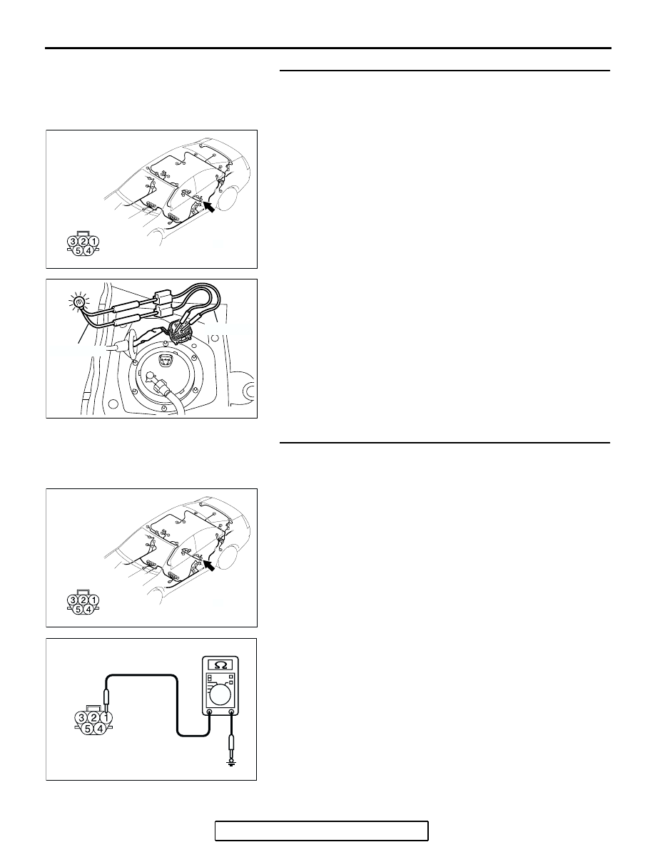
STEP 4. Test at fuel pump module connector D-18 to check 
the power circuit to the fuel pump module.
(1) Remove the rear seat (Refer to GROUP 52A, Rear Seat 

Assembly 

P.52A-29

).

(2) Use special tool MB991219 to connect a test lamp (12 V - 

3.4 W) between the wiring harness connector terminals 1 
and 2.

(3) Turn the Ignition switch to "ON" position.
(4) Check if the test lamp illuminates.

OK: Illuminates

Q: Is the check result satisfactory?

YES : Go to Step 11.
NO :  Go to Step 5.

STEP 5. Measure the resistance at fuel pump module 
connector D-18 to check the ground circuit to the fuel 
pump module.
(1) Disconnect fuel pump module connector D-18, and 

measure at the wiring harness side.

(2) Measure the resistance value between terminal 1 and 

ground.

• The resistance should be 2 ohms or less.

Q: Is the measured resistance 2 ohms or less?

YES : Go to Step 7.
NO :  Go to Step 6.

AC305268

D-18 (GR)

AP

CONNECTOR: D-18

HARNESS SIDE

AC306950

AB

TEST LAMP

MB991219

AC305268

D-18 (GR)

AP

CONNECTOR: D-18

HARNESS SIDE

AC209364

CONNECTOR D-18 
(HARNESS SIDE)

JS

COMBINATION METER ASSEMBLY

TSB Revision

CHASSIS ELECTRICAL

54A-93

STEP 6. Check the wiring harness between fuel pump 
module connector D-18  (terminal 1) and ground.
Q: Is the wiring harness between fuel pump module 

connector D-18 (terminal 1) and ground in good 
condition?
YES : 
Go to Step 7.
NO :  Repair the wiring harness. The fuel gauge should now 

operate normally.

STEP 7. Check combination meter connector C-101 and 
fuel level sensor (sub) connector D-17 for loose, corroded 
or damaged terminals, or terminals pushed back in the 
connector.
Q: Is combination meter connector C-101 and fuel level 

sensor (sub)  connector D-17 in good condition?
YES : 
Go to Step 8.
NO :  Repair or replace the component(s). Refer to GROUP 

00E, Harness Connector Inspection 

P.00E-2

. Then go 

to Step 4.

AC305268

D-18 (GR)

AP

CONNECTOR: D-18

HARNESS SIDE

AC305231CT

CONNECTOR: C-101

HARNESS SIDE

AC305268

AQ

CONNECTOR: D-17

HARNESS SIDE

COMBINATION METER ASSEMBLY

TSB Revision

CHASSIS ELECTRICAL

54A-94

STEP 8. Check the wiring harness between combination 
meter connector C-101 (terminal 13) and fuel level sensor 
(sub) connector D-17 (terminal 2).

NOTE: Also check intermediate connectors C-28 for loose, cor-
roded, or damaged terminals, or terminals pushed back in the 
connector. If intermediate connector C-28 is damaged, repair or 
replace the connector as described in GROUP 00E, Harness 
Connector Inspection 

P.00E-2

.

Q: Is the wiring harness between combination meter 

connector C-101 (terminal 13) and fuel level sensor 
(sub) connector D-17 (terminal 2) in good condition?
YES : 
Go to Step 9.
NO :  Repair the wiring harness. The fuel gauge should now 

operate normally.

AC305268

AQ

CONNECTOR: D-17

HARNESS SIDE

AC305232BA

CONNECTORS: C-28, C-101

C-28

C-101

C-28

HARNESS SIDE

C-101

9

21

33

35

24

12

3 4

7

8

5 6

39

28

41

30

18

4243

31

1920

32

40

29

1617

38

27

15

37

36

26

14

13

25

2

1

34

23

11

10

22

COMBINATION METER ASSEMBLY

TSB Revision

CHASSIS ELECTRICAL

54A-95

STEP 9. Check fuel pump module connector D-18 and fuel 
level sensor (sub) connector D-17 for loose, corroded or 
damaged terminals, or terminals pushed back in the 
connector.
Q: Is fuel pump module connector D-18 and fuel level 

sensor (sub)  connector D-17 in good condition?
YES : 
Go to Step 10.
NO :  Repair or replace the component(s). Refer to GROUP 

00E, Harness Connector Inspection 

P.00E-2

. The fuel 

gauge should now operate normally.

STEP 10. Check the wiring harness between fuel pump 
module connector D-18 (terminal 2) and fuel level sensor 
(sub) connector D-17 (terminal 1).
Q: Is the wiring harness between fuel pump module 

connector D-18 (terminal 2) and fuel level sensor (sub) 
connector D-17 (terminal 1) in good condition?
YES : 
Go to Step 11.
NO :  Repair the wiring harness. The fuel gauge should now 

operate normally.

AC305269

D-17

D-18 (GR)

AE

CONNECTORS: D-17, D-18

HARNESS SIDE

D-17

HARNESS SIDE

D-18

AC305269

D-17

D-18 (GR)

AE

CONNECTORS: D-17, D-18

HARNESS SIDE

D-17

HARNESS SIDE

D-18


Content   ..  1553  1554  1555  1556   ..