Mitsubishi Galant 9G. Manual - part 1550


  Index      Mitsubishi     Mitsubishi Galant 9G - service repair manual


Search            


Content   ..  1548  1549  1550  1551   ..


Mitsubishi Galant 9G. Manual - part 1550


COMBINATION METER ASSEMBLY

TSB Revision

CHASSIS ELECTRICAL

54A-72

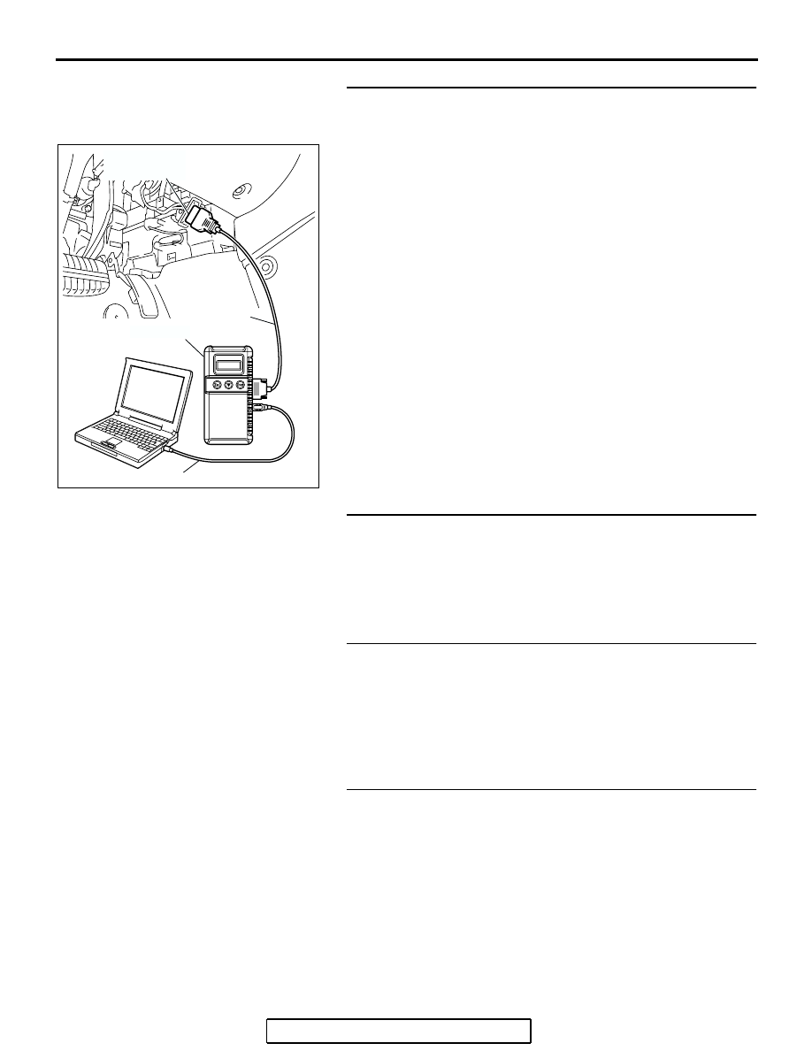
STEP 1. Using scan tool MB991958, diagnose the CAN bus 
line.
Use scan tool MB991958 to diagnose the CAN bus lines.
(1) Connect scan tool MB991958 to the data link connector.
(2) Turn the ignition switch to "ON" position.
(3) Diagnose the CAN bus line.
Q: Is the check result satisfactory?

YES : Go to Step 2.
NO :  Repair the CAN bus lines (Refer to GROUP 54C, 

Diagnosis-Can Bus Diagnostic Chart 

P.54C-14

). On 

completion, go to Step 4.

STEP 2. Using scan tool MB991958, read the ETACS-ECU 
diagnostic trouble code.
Check that the ETACS-ECU sets a DTC.
Q: Is the DTC set?

YES : Diagnose the SWS system by referring to 

P.54B-27

.

NO :  Go to Step 3.

STEP 3. Replace the ETACS-ECU and then recheck the 
DTC.
Replace the ETACS-ECU, and then check that the DTC is not 
reset.
Q: Is the check result satisfactory?

YES : Go to Step 4.
NO :  Replace combination meter and then go to step 4.

STEP 4. Recheck for diagnostic trouble code.
Recheck if the DTC is set.

1. Erase the DTC.
2. Turn the ignition switch to "ON" position.
3. Check if the DTC is set.

Q: Is the check result satisfactory?

YES : The procedure is complete.
NO :  Go to Step 1.

AC305412

AB

MB991910

DATA LINK

CONNECTOR

MB991824

MB991827

COMBINATION METER ASSEMBLY

TSB Revision

CHASSIS ELECTRICAL

54A-73

SYMPTOM CHART

M1543007201116

CAUTION

During diagnosis, a DTC code associated with 
other system may be set when the ignition switch 
is turned on with connector(s) disconnected. On 
completion, confirm all systems for DTC code(s). 
If DTC code(s) are set, erase them all.

SYMPTOM

INSPECTION 
PROCEDURE

REFERENCE PAGE

Communication with scan tool is not possible.

1

P.54A-74

Power supply circuit.

2

P.54A-77

Odometer and trip meter are not displayed.

3

All the needle meters do not work.

4

When the ignition switch is turned to the ON position, the 
indicator and warning lights do not illuminate.

5

Speedometer does not work.

6

P.54A-83

The fuel gauge needle moves excessively.

7

Tachometer does not work.

8

P.54A-87

Fuel Gauge does not work (other meters work).

9

P.54A-90

Engine coolant temperature gauge does not work (other meters 
work).

10

P.54A-97

COMBINATION METER ASSEMBLY

TSB Revision

CHASSIS ELECTRICAL

54A-74

SYMPTOM PROCEDURES

INSPECTION PROCEDURE 1:Communication With Scan Tool is Not Possible.

WITHOUT ELECTRONIC 
BRAKE-FORCE 
DISTRIBUTION (EBD) 
AND ANTI-LOCK 
BRAKING SYSTEM 
(ABS)

WITHOUT ELECTRONIC 
BRAKE-FORCE 
DISTRIBUTION (EBD) 
AND ANTI-LOCK 
BRAKING SYSTEM 
(ABS)

WITH ELECTRONIC 
BRAKE-FORCE 
DISTRIBUTION (EBD) 
AND ANTI-LOCK 
BRAKING SYSTEM 
(ABS)

WITH ELECTRONIC 
BRAKE-FORCE 
DISTRIBUTION (EBD) 
AND ANTI-LOCK 
BRAKING SYSTEM 
(ABS)

ABS-ECU OR ABS/TCL-ECU

JOINT 
CONNECTOR (3)

POWERTRAIN 
CONTROL 
MODULE

COMBINATION 
METER

CPU

DATA LINK CONNECTOR

Combinaton Meter CAN-BUS Line Circuit

COMBINATION METER ASSEMBLY

TSB Revision

CHASSIS ELECTRICAL

54A-75

.

CIRCUIT OPERATION

The combination meter is linked to the data link con-
nector via CAN bus line to communicate with the 
scan tool. 

.

TECHNICAL DESCRIPTION (COMMENT)

If the system does not communicate with scan tool, 
power supply to data link connector or CAN bus lines 
may be defective.

.

TROUBLESHOOTING HINTS

• The wiring harness or connectors may have 

loose, corroded, or damaged terminals, or termi-
nals pushed back in the connector.

AC305206

CONNECTOR: A-02

AO

A-02 (GR)

AC305216

B-19 (B)

CONNECTOR: B-19

AD

AC305231

C-02

C-29

C-101

C-125 (B)

DC

CONNECTORS: C-02, C-29, C-101, C-125


Content   ..  1548  1549  1550  1551   ..