Content .. 1498 1499 1500 1501 ..
Mitsubishi Galant 9G. Manual - part 1500
ON-VEHICLE SERVICE
TSB Revision
FRONT SUSPENSION
33-6
ON-VEHICLE SERVICE
FRONT WHEEL ALIGNMENT CHECK AND
ADJUSTMENT
M1331000900701
Measure wheel alignment with alignment equipment on a level
surface. The front suspension, steering system and tires should
be serviced to normal condition before measuring wheel align-
ment.
.
TOE-IN
Standard value: 0
± 3 mm (0 ± 0.12 inch)
1. Adjust the toe-in by undoing the clip and jam nut, and
turning the left and right tie rod turnbuckles by the same
amount (in opposite directions).
NOTE: The toe will move out as the left turnbuckle is turned
toward the front of the vehicle and the right turnbuckle is
turned toward the rear of the vehicle.
2. Install the clip and tighten the jam nut to the specified
torque.
Tightening torque: 52
± 2 N⋅m (38 ± 2 ft-lb)
3. Confirm that the toe-in is at the standard value.
4. Use a turning radius gauge to check that the steering angle
is at the standard value.
STEERING ANGLE
Standard value:
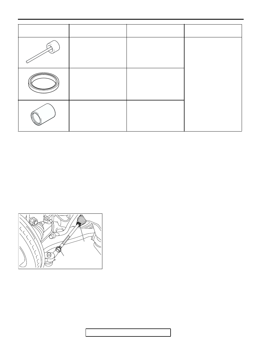
MB991963
Suspension bushing arbor
−
Lower arm bushing
removal and press-fitting
MB990889
Rear suspension bushing
ring
−
MB990890
Rear suspension bushing
base
MB990890-01 or general
service tool
TOOL
TOOL NUMBER AND
NAME
SUPERSESSION
APPLICATION
MB991963
MB990889
MB990890
AC305785
AB
JAM NUT
CLIP