Content .. 1481 1482 1483 1484 ..
Mitsubishi Galant 9G. Manual - part 1483
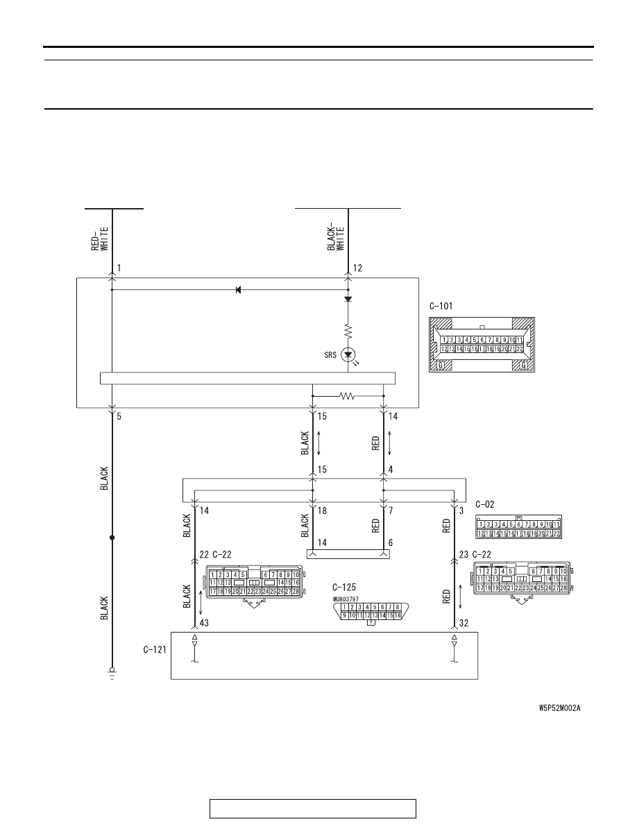
SRS AIR BAG DIAGNOSIS
TSB Revision
SUPPLEMENTAL RESTRAINT SYSTEM (SRS)
52B-342
INSPECTION PROCEDURE 3: When the Ignition Key is Turned to "ON" (Engine Stopped), the SRS
Warning Light does not Illuminate. INSPECTION PROCEDURE 4: The SRS Warning Light Remains
Illuminated after the Engine is Started.
.
AC401937
CPU
COMBINATION
METER
JOINT
CONNECTOR (3)
DATA LINK
CONNECTOR
SRS-ECU
BATTERY
IGNITION SWITCH (IG1)
AB