Mitsubishi Galant 9G. Manual - part 1474


  Index      Mitsubishi     Mitsubishi Galant 9G - service repair manual


Search            


Content   ..  1472  1473  1474  1475   ..


Mitsubishi Galant 9G. Manual - part 1474


SRS AIR BAG DIAGNOSIS

TSB Revision

SUPPLEMENTAL RESTRAINT SYSTEM (SRS)

52B-306

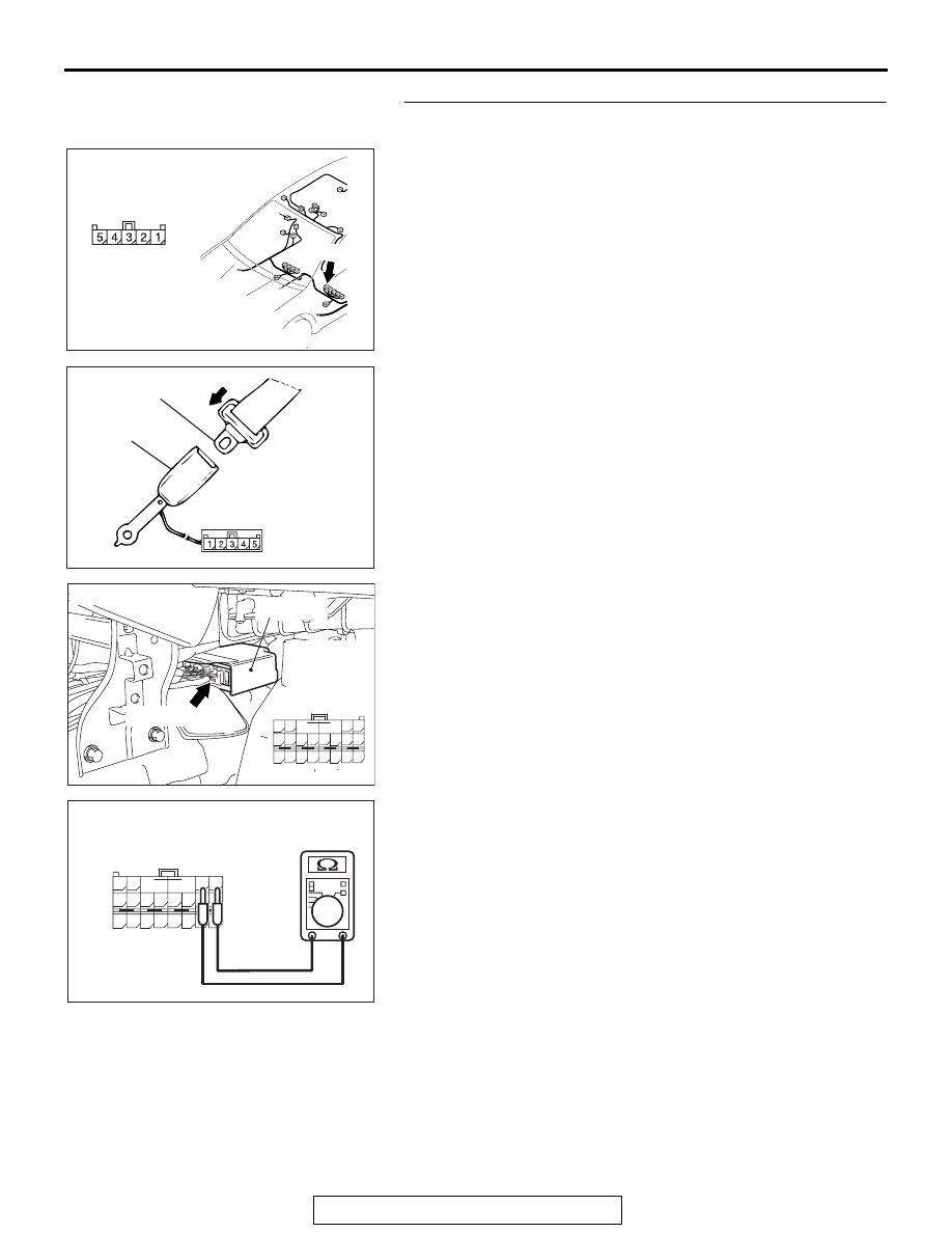
STEP 4. Check the driver’s seat belt switch circuit D-28. 
Measure the resistance at SRS-ECU connector C-122.
(1) Disconnect driver’s seat belt switch connector D-28.

(2) Install the driver’s seat belt to the driver’s seat belt switch.

(3) Disconnect SRS-ECU connector C-122 and measure at the 

harness side (rear side).

(4) Measure the resistance between terminal 3 and terminal 4.

Resistance should be 820 

± 82 Ω

AC305264

AS

CONNECTOR: D-28

D-28 (B)

HARNESS SIDE

AC308221AD

D-28 DRIVER'S 
SEAT BELT SWITCH
CONNECTOR

BUCKLE

TONGUE

AC305362

CONNECTOR: C-122

C-122 (Y)

AI

SRS-ECU

C-122 
Harness side
connector 
(rear view)

A

B

18

10

15

7

13

5

14

6

16

8

17

9

19

11

20

12

1 2

3 4

AC308212

A

B

18

10

15

7

13

5

14

6

16

8

17

9

19

11

20

12

1 2

3 4

C-122 HARNESS SIDE
CONNECTOR
(REAR VIEW)

AB

SRS AIR BAG DIAGNOSIS

TSB Revision

SUPPLEMENTAL RESTRAINT SYSTEM (SRS)

52B-307

(5) Measure the resistance between terminal 3, 4 and body 

ground.
It should be open circuit.

(6) Measure the resistance between terminal 18 and terminal 

4.
Resistance should be less than 2 ohms.

(7) Remove the driver’s seat belt from the driver’s seat belt 

switch.

(8) Disconnect SRS-ECU connector C-122 and measure at the 

harness side (rear side).

(9) Measure the resistance between terminal 18 and 4.

Resistance should be 820 

± 82 Ω

AC310506

A

B

18

10

15

7

13

5

14

6

16

8

17

9

19

11

20

12

1 2

3 4

C-122 HARNESS SIDE
CONNECTOR
(REAR VIEW)

EO

AC308213

A

B

18

10

15

7

13

5

14

6

16

8

17

9

19

11

20

12

1 2

3 4

C-122 HARNESS SIDE
CONNECTOR
(REAR VIEW)

AB

AC308221AC

D-28 DRIVER'S 
SEAT BELT SWITCH
CONNECTOR

BUCKLE

TONGUE

AC305362

CONNECTOR: C-122

C-122 (Y)

AI

SRS-ECU

C-122 
Harness side
connector 
(rear view)

A

B

18

10

15

7

13

5

14

6

16

8

17

9

19

11

20

12

1 2

3 4

AC308213

A

B

18

10

15

7

13

5

14

6

16

8

17

9

19

11

20

12

1 2

3 4

C-122 HARNESS SIDE
CONNECTOR
(REAR VIEW)

AB

SRS AIR BAG DIAGNOSIS

TSB Revision

SUPPLEMENTAL RESTRAINT SYSTEM (SRS)

52B-308

(10)Measure the resistance between terminal 18, 4 and body 

ground.
It should be open circuit.

(11)Measure the resistance between terminal 3 and terminal 4.

Resistance should be less than 2 ohms.

Q: Does the resistance meet the value above?

YES : Erase the diagnostic trouble code memory, and check 

the diagnostic trouble code. If DTC B1520, B1521, 
B1522, B1523, B1524, B1525, B1526, B1527, B1528 
or B1529 are set, replace the SRS-ECU. (Refer to 

P.52B-365

.) Then go to Step 6. 

NO :  Go to Step 5.

STEP 5. Check the harness wires between SRS-ECU 
connector C-122 (terminal No.3, 18 and 4) and driver’s seat 
belt switch connector D-28 (terminal No.3, 4 and 5).
Q: Are harness wires between SRS-ECU connector C-122 

(terminal No.3, 18 and 4) and driver’s seat belt switch 
connector D-28 (terminal No.3, 4 and 5) in good 
condition?
YES : 
Go to Step 6.
NO :  Replace the harness wires between SRS-ECU 

connector C-122 and driver’s seat belt switch 
connector D-28. Then go to Step 6.

AC310506

A

B

18

10

15

7

13

5

14

6

16

8

17

9

19

11

20

12

1 2

3 4

C-122 HARNESS SIDE
CONNECTOR
(REAR VIEW)

EP

AC308212

A

B

18

10

15

7

13

5

14

6

16

8

17

9

19

11

20

12

1 2

3 4

C-122 HARNESS SIDE
CONNECTOR
(REAR VIEW)

AB

AC305362

CONNECTOR: C-122

C-122 (Y)

AI

SRS-ECU

C-122 
Harness side
connector 
(rear view)

A

B

18

10

15

7

13

5

14

6

16

8

17

9

19

11

20

12

1 2

3 4

AC305264

AS

CONNECTOR: D-28

D-28 (B)

HARNESS SIDE

SRS AIR BAG DIAGNOSIS

TSB Revision

SUPPLEMENTAL RESTRAINT SYSTEM (SRS)

52B-309

STEP 6. Recheck for diagnostic trouble code. 
Check again if the DTC is set.
(1) Erase the DTC.
(2) Turn the ignition switch to the "ON" position.
(3) Check if the DTC is set.
(4) Turn the ignition switch to the "LOCK" (OFF) position.

Q: Is DTC B1520, B1521, B1522, B1523, B1524, B1525, 

B1526, B1527, B1528 or B1529 set?
YES : 
Return to Step 1. 
NO :  The procedure is complete.

AC305412

AB

MB991910

DATA LINK

CONNECTOR

MB991824

MB991827


Content   ..  1472  1473  1474  1475   ..