Mitsubishi Galant 9G. Manual - part 1471


  Index      Mitsubishi     Mitsubishi Galant 9G - service repair manual


Search            


Content   ..  1469  1470  1471  1472   ..


Mitsubishi Galant 9G. Manual - part 1471


SRS AIR BAG DIAGNOSIS

TSB Revision

SUPPLEMENTAL RESTRAINT SYSTEM (SRS)

52B-294

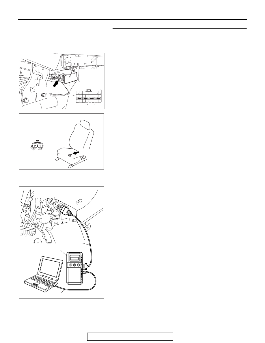
STEP 5. Check the harness wires for short circuit to power 
supply between SRS-ECU connector C-122 (terminal No.2 
and 1) and seat slide sensor connector D-27 (terminal No.1 
and 2).
Q: Are the harness wires between SRS-ECU connector 

C-122 (terminal No.2 and 1) and seat slide sensor 
connector D-27 (terminal No.1 and 2) in good condition?
YES : 
Go to Step 6.
NO :  Replace the harness wires between SRS-ECU 

connector C-122 and seat slide sensor connector 
D-27. Then go to Step 6.

STEP 6. Recheck for diagnostic trouble code. 
Check again if the DTC is set.
(1) Erase the DTC.
(2) Turn the ignition switch to the "ON" position.
(3) Check if the DTC is set.
(4) Turn the ignition switch to the "LOCK" (OFF) position.

Q: Is DTC B1508 set?

YES : Return to Step 1. 
NO :  The procedure is complete.

AC305362

CONNECTOR: C-122

C-122 (Y)

AI

SRS-ECU

C-122 
Harness side
connector 
(rear view)

A

B

18

10

15

7

13

5

14

6

16

8

17

9

19

11

20

12

1 2

3 4

AC308165

CONNECTOR : D-27

AC

D-27 (GR)

HARNESS SIDE

AC305412

AB

MB991910

DATA LINK

CONNECTOR

MB991824

MB991827

SRS AIR BAG DIAGNOSIS

TSB Revision

SUPPLEMENTAL RESTRAINT SYSTEM (SRS)

52B-295

DTC B1509: Improper installation of SRS-ECU

CAUTION

If DTC B1509 is set in the SRS-ECU, always diag-
nose the CAN main bus line.

.

TROUBLE JUDGMENT

This DTC is set when an SRS-ECU, designed only 
for the driver's air bag, is installed on the vehicle, 
which has both driver's and passenger's air bags.

.

TROUBLESHOOTING HINTS

• Malfunction of the SRS-ECU

.

DIAGNOSIS

Required Special Tool:

•  MB991958: Scan Tool (MUT-III Sub Assembly)

• MB991824: Vehicle Communication Interface (V.C.I.)

• MB991827: MUT-III USB Cable

• MB991910: MUT-III Main Harness A (Vehicles with CAN 

communication system)

STEP 1. Using scan tool MB991958, diagnose the CAN bus 
line.

CAUTION

To prevent damage to scan tool MB991958, always turn the 
ignition switch to the "LOCK" (OFF) position before con-
necting or disconnecting scan tool MB991958.
(1) Connect scan tool MB991958. Refer to "How to connect the 

scan tool 

P.52B-30

."

(2) Turn the ignition switch to the "ON" position.
(3) Diagnose the CAN bus line.
(4) Turn the ignition switch to the "LOCK" (OFF) position.

Q: Is the CAN bus line found to be normal?

YES : Go to Step 2.
NO :  Repair the CAN bus line (Refer to GROUP 54C, 

Diagnosis ).

AC305412

AB

MB991910

DATA LINK

CONNECTOR

MB991824

MB991827

SRS AIR BAG DIAGNOSIS

TSB Revision

SUPPLEMENTAL RESTRAINT SYSTEM (SRS)

52B-296

STEP 2. Recheck for diagnostic trouble code.
Check again if the DTC is set.
(1) Erase the DTC.
(2) Turn the ignition switch to the "ON" position.
(3) Check if the DTC is set.
(4) Turn the ignition switch to the "LOCK" (OFF) position.

Q: Is the DTC B1499 set?

YES : Replace the SRS-ECU (Refer to 

P.52B-365

).

NO :  There is an intermittent malfunction such as poor 

engaged connector(s) or open circuit (Refer to 
GROUP 00, How to Use Troubleshooting/Inspection 
Service Points 

− How to Cope with Intermittent 

Malfunctions ).

DTC B1519: Connector Lock System Detects Connector Unlocked

CAUTION

If DTC B1519 is set in the SRS-ECU, always diag-
nose the CAN main bus line.

.

DTC SET CONDITIONS

This DTC is set if a poor connection at the SRS-ECU 
is detected. However, if the vehicle condition returns 
to normal, DTC number B1519 will be automatically 
erased, and the SRS warning light will go out.

.

TROUBLESHOOTING HINTS

• Damaged connectors

• Malfunction of the SRS-ECU

.

DIAGNOSIS

Required Special Tool:

•  MB991958: Scan Tool (MUT-III Sub Assembly)

• MB991824: Vehicle Communication Interface (V.C.I.)

• MB991827: MUT-III USB Cable

• MB991910: MUT-III Main Harness A (Vehicles with CAN 

communication system)

AC305412

AB

MB991910

DATA LINK

CONNECTOR

MB991824

MB991827

SRS AIR BAG DIAGNOSIS

TSB Revision

SUPPLEMENTAL RESTRAINT SYSTEM (SRS)

52B-297

STEP 1. Using scan tool MB991958, diagnose the CAN bus 
line.

CAUTION

To prevent damage to scan tool MB991958, always turn the 
ignition switch to the "LOCK" (OFF) position before con-
necting or disconnecting scan tool MB991958.
(1) Connect scan tool MB991958. Refer to "How to connect the 

scan tool 

P.52B-30

.."

(2) Turn the ignition switch to the "ON" position.
(3) Diagnose the CAN bus line.
(4) Turn the ignition switch to the "LOCK" (OFF) position.

Q: Is the CAN bus line found to be normal?

YES : Go to Step 2.
NO :  Repair the CAN bus line (Refer to GROUP 54C, 

Diagnosis ).

STEP 2. Recheck for diagnostic trouble code.
Check again if the DTC is set.
(1) Erase the DTC.
(2) Turn the ignition switch to "ON" position.
(3) Check if the DTC is set.
(4) Turn the ignition switch to the "LOCK" (OFF) position.

Q: Is the DTC set?

YES : Go to Step 3. 
NO :  There is an intermittent malfunction such as poor 

engaged connector(s) or open circuit (Refer to 
GROUP 00, How to Use Troubleshooting/Inspection 
Service Points 

− How to Cope with Intermittent 

Malfunctions ).

AC305412

AB

MB991910

DATA LINK

CONNECTOR

MB991824

MB991827

AC305412

AB

MB991910

DATA LINK

CONNECTOR

MB991824

MB991827


Content   ..  1469  1470  1471  1472   ..