Mitsubishi Galant 9G. Manual - part 1467


  Index      Mitsubishi     Mitsubishi Galant 9G - service repair manual


Search            


Content   ..  1465  1466  1467  1468   ..


Mitsubishi Galant 9G. Manual - part 1467


SRS AIR BAG DIAGNOSIS

TSB Revision

SUPPLEMENTAL RESTRAINT SYSTEM (SRS)

52B-278

STEP 6. Recheck for diagnostic trouble code.
Check again if the DTC is set.
(1) Erase the DTC.
(2) Turn the ignition switch to the "ON" position.
(3) Check if the DTC is set.
(4) Turn the ignition switch to the "LOCK" (OFF) position.

Q: Is DTC B1489 set?

YES : Return to Step 1. 
NO :  The procedure is complete.

DTC B1499: SRS-ECU Air Bag Condition Monitor Detects Deployed Air Bag 

CAUTION

If DTC B1499 is set in the SRS-ECU, always diag-
nose the CAN main bus line.

.

DTC SET CONDITIONS

This DTC is set after the air bag has deployed. If this 
DTC is set before the air bag has deployed, the 
cause is probably a malfunction inside the 
SRS-ECU.

.

TROUBLESHOOTING HINTS

Malfunction of the SRS-ECU

.

DIAGNOSIS

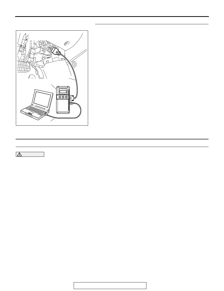
Required Special Tool:

• MB991958: Scan Tool (MUT-III Sub Assembly)

• MB991824: Vehicle Communication Interface (V.C.I.)

• MB991827: MUT-III USB Cable

• MB991910: MUT-III Main Harness A (Vehicles with CAN 

communication system)

AC305412

AB

MB991910

DATA LINK

CONNECTOR

MB991824

MB991827

SRS AIR BAG DIAGNOSIS

TSB Revision

SUPPLEMENTAL RESTRAINT SYSTEM (SRS)

52B-279

STEP 1. Using scan tool MB991958, diagnose the CAN bus 
line.

CAUTION

To prevent damage to scan tool MB991958, always turn the 
ignition switch to the "LOCK" (OFF) position before con-
necting or disconnecting scan tool MB991958.
(1) Connect scan tool MB991958. Refer to "How to connect the 

scan tool 

P.52B-30

."

(2) Turn the ignition switch to the "ON" position.
(3) Diagnose the CAN bus line.
(4) Turn the ignition switch to the "LOCK" (OFF) position.

Q: Is the CAN bus line found to be normal?

YES : Go to Step 2.
NO :  Repair the CAN bus line (Refer to GROUP 54C, 

Diagnosis ).

STEP 2. Recheck for diagnostic trouble code.
Check again if the DTC is set.
(1) Erase the DTC.
(2) Turn the ignition switch to the "ON" position.
(3) Check if the DTC is set.
(4) Turn the ignition switch to the "LOCK" (OFF) position.

Q: Is the DTC B1499 set?

YES : Replace the SRS-ECU (Refer to 

P.52B-365

).

NO :  There is an intermittent malfunction such as poor 

engaged connector(s) or open circuit (Refer to 
GROUP 00, How to Use Troubleshooting/Inspection 
Service Points 

− How to Cope with Intermittent 

Malfunctions ).

AC305412

AB

MB991910

DATA LINK

CONNECTOR

MB991824

MB991827

AC305412

AB

MB991910

DATA LINK

CONNECTOR

MB991824

MB991827

SRS AIR BAG DIAGNOSIS

TSB Revision

SUPPLEMENTAL RESTRAINT SYSTEM (SRS)

52B-280

DTC B1506: Seat Slide Sensor System Fault 1 (Open in the Seat Slide Sensor Circuit)

CAUTION

If DTC B1506 is set in the SRS-ECU, always diag-
nose the CAN main bus line.

.

CIRCUIT OPERATION

• The seat slide sensor sets the current value Hi or 

Low determined by the seat position.

• The SRS-ECU determines the seat position 

according to the current value from the seat slide 
sensor.

.

DTC SET CONDITIONS

• This DTC is set if there is abnormal resistance 

between the input terminals of the seat slide sen-
sor. The most likely causes for this code to be set 
are the followings: 

• Open circuit in the seat slide sensor or har-

ness

• Malfunction of connector contact

However, if no DTC reset, the SRS warning light will 
be switched off (DTC will be retained). 

.

TROUBLESHOOTING HINTS

• Open circuit in the seat slide sensor circuit

• Disengaged seat slide sensor connector

• Improper connector contact

• Malfunction of the SRS-ECU

.

  Seat Slide Sensor Circuit

SEAT SLIDE
SENSOR

HALL IC

SEAT SLIDE SENSOR
DETECTION CIRCUIT

SRS-ECU

AC305362

CONNECTOR: C-122

C-122 (Y)

AE

SRS-ECU

AC308165

CONNECTOR : D-27

AB

D-27 (GR)

SRS AIR BAG DIAGNOSIS

TSB Revision

SUPPLEMENTAL RESTRAINT SYSTEM (SRS)

52B-281

DIAGNOSIS

Required Special Tools:

• MB991958: Scan Tool (MUT-III Sub Assembly)

• MB991824: Vehicle Communication Interface (V.C.I.)

• MB991827: MUT-III USB Cable

• MB991910: MUT-III Main Harness A (Vehicles with CAN 

Communication System)

• MB991865: Dummy resistor

• MB991866: Resister harness

STEP 1. Using scan tool MB991958, diagnose the CAN bus 
line.

CAUTION

To prevent damage to scan tool MB991958, always turn the 
ignition switch to the "LOCK" (OFF) position before con-
necting or disconnecting scan tool MB991958.
(1) Connect scan tool MB991958. Refer to "How to connect the 

scan tool 

P.52B-30

."

(2) Turn the ignition switch to the "ON" position.
(3) Diagnose the CAN bus line.
(4) Turn the ignition switch to the "LOCK" (OFF) position.

Q: Is the CAN bus line found to be normal?

YES : Go to Step 2.
NO :  Repair the CAN bus line (Refer to GROUP 54C, 

Diagnosis ).

AC305412

AB

MB991910

DATA LINK

CONNECTOR

MB991824

MB991827


Content   ..  1465  1466  1467  1468   ..