Mitsubishi Galant 9G. Manual - part 1456


  Index      Mitsubishi     Mitsubishi Galant 9G - service repair manual


Search            


Content   ..  1454  1455  1456  1457   ..


Mitsubishi Galant 9G. Manual - part 1456


SRS AIR BAG DIAGNOSIS

TSB Revision

SUPPLEMENTAL RESTRAINT SYSTEM (SRS)

52B-234

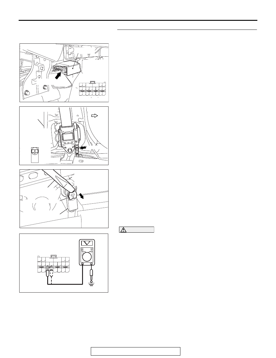
STEP 4. Check the driver's seat belt pre-tensioner circuit. 
Measure the resistance at the SRS-ECU connector C-122.
(1) Disconnect SRS-ECU connector C-122.

(2) Disconnect driver's seat belt pre-tensioner connector D-21. 

Use a flat-tipped screwdriver to unlock the locking button at 
the harness side connector by withdrawing it toward you in 
two stages, and then disconnect the connector.

CAUTION

Do not insert a test probe into the terminal from its front 
side directly, as the connector contact pressure may be 
weakened.
(3) Check for continuity between C-122 harness side connector 

terminals 7, 8 and body ground.
It should be open circuit.

Q: Does continuity exist?

YES : Go to Step 5.
NO :  Erase the diagnostic trouble code memory, and check 

the diagnostic trouble code. If DTC B1473 sets, 
replace the SRS-ECU (Refer to 

P.52B-365

). Then go 

to Step 6.

AC305362

CONNECTOR: C-122

C-122 (Y)

AI

SRS-ECU

C-122 
Harness side
connector 
(rear view)

A

B

18

10

15

7

13

5

14

6

16

8

17

9

19

11

20

12

1 2

3 4

AC306920AC

CONNECTOR: D-21

D-21 (B)

FOWARD

CENTER
PILLAR

HARNESS SIDE
CONNECTOR
(FRONT VIEW)

2 1

AC103556 AT

LOCKING BUTTON

FLAT-TIP SCREW
DRIVER

D-21 HARNESS 
SIDE CONNECTOR

D-21 DRIVER'S 
SEAT BELT
PRE-TENSIONER
CONNECTOR

AC308181

A

B

18

10

15

7

13

5

14

6

16

8

17

9

19

11

20

12

1 2

3 4

AB

C-122 HARNESS SIDE
CONNECTOR
(REAR VIEW)

SRS AIR BAG DIAGNOSIS

TSB Revision

SUPPLEMENTAL RESTRAINT SYSTEM (SRS)

52B-235

STEP 5. Check harness wires for short circuit to ground 
between SRS-ECU connector C-122 (terminal No.7 and 8) 
and driver's seat belt pre-tensioner connector D-21 
(terminal No.1 and 2).
Q: Are the harness wires between SRS-ECU connector 

C-122 (terminal No.7 and 8) and driver's seat belt 
pre-tensioner connector D-21 (terminal No.1 and 2) in 
good condition?
YES : 
Go to Step 6.
NO :  Replace the harness wires between SRS-ECU 

connector C-122 and driver's seat belt pre-tensioner 
connector D-26. Then go to Step 6.

STEP 6. Recheck for diagnostic trouble code. 
Check again if the DTC is set.
(1) Erase the DTC.
(2) Turn the ignition switch to the "ON" position.
(3) Check if the DTC is set.
(4) Turn the ignition switch to the "LOCK" (OFF) position.

Q: Is DTC B1473 set?

YES : Return to Step 1. 
NO :  The procedure is complete. 

AC305362

CONNECTOR: C-122

C-122 (Y)

AI

SRS-ECU

C-122 
Harness side
connector 
(rear view)

A

B

18

10

15

7

13

5

14

6

16

8

17

9

19

11

20

12

1 2

3 4

AC306920AC

CONNECTOR: D-21

D-21 (B)

FOWARD

CENTER
PILLAR

HARNESS SIDE
CONNECTOR
(FRONT VIEW)

2 1

AC305412

AB

MB991910

DATA LINK

CONNECTOR

MB991824

MB991827

SRS AIR BAG DIAGNOSIS

TSB Revision

SUPPLEMENTAL RESTRAINT SYSTEM (SRS)

52B-236

DTC B1476: IG1 Power Supply Circuit System (Fuse No.22 Circuit) DTC B1477: IG1 Power Supply 
Circuit System (Fuse No.23 Circuit)

IG1 Power Supply Circuit

IGNITION
SWITCH (IG1)

JUNCTION
BLOCK

SRS-ECU

AC305233 AO

CONNECTOR: C-22

C-22 (Y)

AC305362

CONNECTOR: C-121

C-121 (Y)

AD

SRS-ECU

SRS AIR BAG DIAGNOSIS

TSB Revision

SUPPLEMENTAL RESTRAINT SYSTEM (SRS)

52B-237

CAUTION

If DTC B1476 <Fuse No.22> or B1477 <Fuse 
No.23> is set in the combination meter, always 
diagnose the CAN bus lines.

.

CIRCUIT OPERATION

• The SRS-ECU is powered from the ignition 

switch (IG1).

• The SRS-ECU power is supplied from two cir-

cuits. Even if one circuit is shut off, the air bag 
can inflate.

.

DTC SET CONDITIONS

This DTC is set if the voltage between the IG1 termi-
nals (fuse No.22 circuit or fuse No.23 circuit) and 
ground is lower than a predetermined value for a 
continuous period of five second or more. However, if 
the vehicle condition returns to normal, DTC number 
B1476 <Fuse No.22> or B1477 <Fuse No.23> will be 
automatically erased, and the SRS warning light will 
switch off.

.

TROUBLESHOOTING HINTS

• Damaged wiring harnesses or connectors

• Malfunction of the SRS-ECU

.

DIAGNOSIS

Required Special Tools:

•  MB991958: Scan Tool (MUT-III Sub Assembly)

• MB991824: Vehicle Communication Interface (V.C.I.)

• MB991827: MUT-III USB Cable

• MB991910: MUT-III Main Harness A (Vehicles with CAN 

communication system)

• MB991223 (MB991222): Harness set (Probe)

AC305415

C-211

C-214

CONNECTORS: C-211, C-214

AR


Content   ..  1454  1455  1456  1457   ..