Mitsubishi Galant 9G. Manual - part 1453


  Index      Mitsubishi     Mitsubishi Galant 9G - service repair manual


Search            


Content   ..  1451  1452  1453  1454   ..


Mitsubishi Galant 9G. Manual - part 1453


SRS AIR BAG DIAGNOSIS

TSB Revision

SUPPLEMENTAL RESTRAINT SYSTEM (SRS)

52B-222

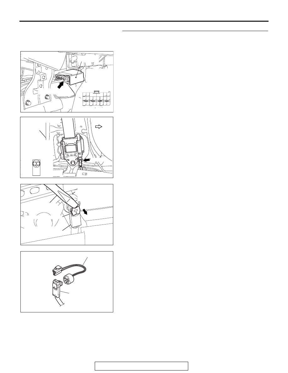
STEP 4. Check the harness for open circuit between 
SRS-ECU connector C-122 (terminal No.7 and 8) and the 
driver's seat belt pre-tensioner D-21 (terminal No.1 and 2).
(1) Disconnect SRS-ECU connector C-122 and driver's seat 

belt pre-tensioner connector D-21, and measure at the 
wiring harness side. For connector D-21, use a flat-tipped 
screwdriver to unlock the locking button at the harness side 
connector by withdrawing it toward you in two stages, and 
then disconnect the connector.

(2) Connect D-21 harness side connector to special tool 

MB991884.

AC305362

CONNECTOR: C-122

C-122 (Y)

AI

SRS-ECU

C-122 
Harness side
connector 
(rear view)

A

B

18

10

15

7

13

5

14

6

16

8

17

9

19

11

20

12

1 2

3 4

AC306920AC

CONNECTOR: D-21

D-21 (B)

FOWARD

CENTER
PILLAR

HARNESS SIDE
CONNECTOR
(FRONT VIEW)

2 1

AC103556 AT

LOCKING BUTTON

FLAT-TIP SCREW
DRIVER

D-21 HARNESS 
SIDE CONNECTOR

D-21 DRIVER'S 
SEAT BELT
PRE-TENSIONER
CONNECTOR

AC201287AT

D-21
HARNESS SIDE 
CONNECTOR

MB991884

SRS AIR BAG DIAGNOSIS

TSB Revision

SUPPLEMENTAL RESTRAINT SYSTEM (SRS)

52B-223

CAUTION

Do not insert a test probe into the terminal from its front 
side directly, as the connector contact pressure may be 
weakened.
(3) Check for continuity between the following terminals. It 

should be less than 2 ohms.

• SRS-ECU connector C-122 (terminal No.7) and the spe-

cial tool (terminal No.2)

• SRS-ECU connector C-122 (terminal No.8) and the spe-

cial tool (terminal No.1)

Q: Does continuity exist?

YES : Erase the diagnostic trouble code memory, and 

recheck if any DTC set. If DTC B1471 set, replace the 
SRS-ECU (Refer to 

P.52B-365

). Then go to Step 5.

NO :  Replace harness wires between SRS-ECU connector 

C-122 and driver’s seat belt pre-tensioner connector 
D-21. Then go to Step 5.

STEP 5. Check for diagnostic trouble code.
Check again if the DTC is set.
(1) Erase the DTC.
(2) Turn the ignition switch to the "ON" position.
(3) Check if the DTC is set.
(4) Turn the ignition switch to the "LOCK" (OFF) position.

Q: Is DTC B1471 set?

YES : Return to Step 1. 
NO :  The procedure is complete.

AC308183

2

1

A

B

18

10

15

7

13

5

14

6

16

8

17

9

19

11

20

12

1 2

3 4

AB

<D-21 HARNESS SIDE
CONNECTOR>
SPECIAL TOOL
MB991884
(FRONT VIEW)

C-122 HARNESS SIDE
CONNECTOR
(REAR VIEW)

AC305412

AB

MB991910

DATA LINK

CONNECTOR

MB991824

MB991827

SRS AIR BAG DIAGNOSIS

TSB Revision

SUPPLEMENTAL RESTRAINT SYSTEM (SRS)

52B-224

DTC B1472: Seat Belt Pre-Tensioner (LH) (Squib) System Fault for Power Supply Circuit (Short-Circuit 
to Power Supply)

CAUTION

If DTC B1472 is set in the SRS-ECU, always diag-
nose the CAN main bus line.

.

CIRCUIT OPERATION

The SRS-ECU judges how severe a collision is by 
detecting signals from the front impact sensors and 
the front air bag analog G-sensor. If the impact is 
over a predetermined level, the SRS-ECU sends an 
ignition signal. At this time, if the front air bag safing 
G-sensor is on, the pre-tensioner will deploy. 

.

DTC SET CONDITIONS

This DTC is set if there is abnormal resistance 
between the input terminals of the driver's seat belt 
pre-tensioner (squib).

.

TROUBLESHOOTING HITS

• Damaged wiring harnesses or connectors

• Short to the power supply in the driver's seat belt 

pre-tensioner (squib) harness

• Malfunction of the SRS-ECU

.

Driver's Seat Belt Pre-Tensioner (Squib) Circuit

SEAT BELT
PRE-TENSIONER
(LH)

PRE-TENSIONER(LH)
DRIVE CIRCUIT

SRS-ECU

CONNECTOR
LOCK SWITCH

CONNECTOR
LOCK SWITCH

: CONNECTOR CONNECTED: ON
  CONNECTOR DICONNECTED: OFF

NOTE

AC305362

CONNECTOR: C-122

C-122 (Y)

AE

SRS-ECU

AC306920AB

CONNECTOR: D-21

D-21 (B)

FOWARD

CENTER
PILLAR

SRS AIR BAG DIAGNOSIS

TSB Revision

SUPPLEMENTAL RESTRAINT SYSTEM (SRS)

52B-225

DIAGNOSIS

Required Special Tools:

• MB991958: Scan Tool (MUT-III Sub Assembly)

• MB991824: Vehicle Communication Interface (V.C.I.)

• MB991827: MUT-III USB Cable

• MB991910: MUT-III Main Harness A

• MB991865: Dummy resistor

• MB991884: Resister harness (For Pre-tensioner)

STEP 1. Using scan tool MB991958, diagnose the CAN bus 
line.

CAUTION

To prevent damage to scan tool MB991958, always turn the 
ignition switch to the "LOCK" (OFF) position before con-
necting or disconnecting scan tool MB991958.
(1) Connect scan tool MB991958. Refer to "How to connect the 

scan tool 

P.52B-30

."

(2) Turn the ignition switch to the "ON" position.
(3) Diagnose the CAN bus line.
(4) Turn the ignition switch to the "LOCK" (OFF) position.

Q: Is the CAN bus line found to be normal?

YES : Go to Step 2.
NO :  Repair the CAN bus line (Refer to GROUP 54C, 

Diagnosis ).

AC305412

AB

MB991910

DATA LINK

CONNECTOR

MB991824

MB991827


Content   ..  1451  1452  1453  1454   ..