Mitsubishi Galant 9G. Manual - part 1426


  Index      Mitsubishi     Mitsubishi Galant 9G - service repair manual


Search            


Content   ..  1424  1425  1426  1427   ..


Mitsubishi Galant 9G. Manual - part 1426


SRS AIR BAG DIAGNOSIS

TSB Revision

SUPPLEMENTAL RESTRAINT SYSTEM (SRS)

52B-114

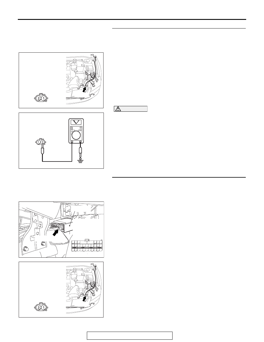
STEP 3. Check the front impact sensor (LH) power supply 
circuit. Measure the voltage at the front impact sensor (LH) 
connector A-23.
(1) Disconnect the negative battery terminal.
(2) Disconnect front impact sensor (LH) connector A-23, and 

measure at the wiring harness side.

(3) Connect the negative battery terminal.
(4) Turn the ignition switch to the "ON" position.

CAUTION

Do not insert a test probe into the terminal from its front 
side directly, as the connector contact pressure may be 
weakened.
(5) Measure the voltage between A-23 harness side connector 

terminal 2 and ground.
Voltage should measure 9 volts or more

Q: Is the measured voltage within the specified range?

YES : Replace the front impact sensor (LH) (Refer to 

P.52B-362

). Then go to Step 5.

NO :  Go to Step 4.

STEP 4. Check the harness wires for open circuit or short 
circuit between SRS-ECU connector C-121 (terminal No.38 
and 39) and front impact sensor (LH) connector A-23 
(terminal No.1 and 2).

AC305210

CONNECTOR: A-23

AT

A-23 (Y)

HARNESS SIDE

AC308161

A-23 HARNESS SIDE
CONNECTOR
(REAR VIEW)

AC

AC305362

CONNECTOR: C-121

C-121 (Y)

AH

SRS-ECU

C-121
HARNESS SIDE 
CONNECTOR
(REAR VIEW)

42

31

38

27

21

41

28

39

22

30

25

47

36

33

44

34

45

37

48

26

29

23

40

32

43

35

46

24

B

A

AC305210

CONNECTOR: A-23

AT

A-23 (Y)

HARNESS SIDE

SRS AIR BAG DIAGNOSIS

TSB Revision

SUPPLEMENTAL RESTRAINT SYSTEM (SRS)

52B-115

NOTE: After inspecting intermediate connectors C-22 and C-29 
inspect the wiring harness. If the intermediate connectors C-22 
and C-29 is damaged, repair or replace it.

Q: Are the harness wires between SRS-ECU connector 

C-121 (terminal No.38 and 39) and front impact sensor 
(LH) connector A-23 (terminal No.1 and 2) in good 
condition?
YES : 
Erase the diagnostic trouble code memory, and check 

the diagnostic trouble code. If DTC B1417 sets, 
replace the SRS-ECU (Refer to 

P.52B-365

). Then go 

to Step 5.

NO :  Replace the harness wires between SRS-ECU 

connector C-121 and front impact sensor (LH) 
connector A-23. Then go to Step 5.

STEP 5. Recheck for diagnostic trouble code.
Check again if the DTC is set.
(1) Erase the DTC.
(2) Turn the ignition switch to the "ON" position.
(3) Check if the DTC is set.
(4) Turn the ignition switch to the "LOCK" (OFF) position.

Q: Is DTC B1417 set?

YES : Return to Step 1.
NO :  The procedure is complete.

AC305233 AI

CONNECTOR: C-22

C-22 (Y)

AC305231AI

CONNECTOR: C-29

AC305412

AB

MB991910

DATA LINK

CONNECTOR

MB991824

MB991827

SRS AIR BAG DIAGNOSIS

TSB Revision

SUPPLEMENTAL RESTRAINT SYSTEM (SRS)

52B-116

DTC B1418: Front Impact Sensor (LH) (Squib) for Power Supply Circuit
DTC B1419: Front Impact Sensor (LH) (Squib) for Communication System

CAUTION

If DTC B1418 or B1419 is set in the SRS-ECU, 
always diagnose the CAN main bus line.

.

Front Impact Sensor Circuit

INTERFACE CIRCUIT

SRS-ECU

FRONT IMPACT
SENSOR (LH)

FRONT IMPACT 
SENSOR (RH)

AC305210

CONNECTOR: A-23

AW

A-23 (Y)

AC305233 AO

CONNECTOR: C-22

C-22 (Y)

AC305231BF

CONNECTOR: C-29

AC305362

CONNECTOR: C-121

C-121 (Y)

AD

SRS-ECU

SRS AIR BAG DIAGNOSIS

TSB Revision

SUPPLEMENTAL RESTRAINT SYSTEM (SRS)

52B-117

CIRCUIT OPERATION

The front impact sensor includes an analog G sensor 
and CPU, etc. The CPU monitors the analog G sen-
sor output signal. If the CPU judges that the front air 
bags should be deployed, it sends a fire signal to the 
SRS-ECU to deploy the front air bags. In addition, 
the CPU diagnoses the internal components of the 
front impact sensor. If a malfunction occurs, it 
requests the SRS-ECU to set a diagnostic trouble 
code.

.

DTC SET CONDITIONS

These DTCs are set if communication between the 
front impact sensor (LH) and the SRS-ECU is not 
possible or faulty.

.

TROUBLESHOOTING HINTS

• Damaged wiring harnesses or connectors

• Malfunction of the front impact sensor (LH)

• Malfunction of the SRS-ECU

.

DIAGNOSIS

Required Special Tool:

• MB991958: Scan Tool (MUT-III Sub Assembly)

• MB991824: Vehicle Communication Interface (V.C.I.)

• MB991827: MUT-III USB Cable

• MB991910: MUT-III Main Harness A (Vehicles with CAN 

communication system)

• MB991223 (MB991222): Harness set (Probe)

STEP 1. Using scan tool MB991958, diagnose the CAN bus 
line.

CAUTION

To prevent damage to scan tool MB991958, always turn the 
ignition switch to the "LOCK" (OFF) position before con-
necting or disconnecting scan tool MB991958.
(1) Connect scan tool MB991958. Refer to "How to connect the 

scan tool 

P.52B-30

."

(2) Turn the ignition switch to the "ON" position.
(3) Diagnose the CAN bus line.
(4) Turn the ignition switch to the "LOCK" (OFF) position.

Q: Is the CAN bus line found to be normal?

YES : Go to Step 2.
NO :  Repair the CAN bus line (Refer to GROUP 54C, 

Diagnosis ).

AC305412

AB

MB991910

DATA LINK

CONNECTOR

MB991824

MB991827


Content   ..  1424  1425  1426  1427   ..