Mitsubishi Galant 9G. Manual - part 1417


  Index      Mitsubishi     Mitsubishi Galant 9G - service repair manual


Search            


Content   ..  1415  1416  1417  1418   ..


Mitsubishi Galant 9G. Manual - part 1417


SRS AIR BAG DIAGNOSIS

TSB Revision

SUPPLEMENTAL RESTRAINT SYSTEM (SRS)

52B-78

CIRCUIT OPERATION

The front impact sensor includes an analog G sensor 
and CPU, etc. The CPU monitors the analog G sen-
sor output signal. If the CPU judges that the front air 
bags should be deployed, it sends a fire signal to the 
SRS-ECU to deploy the front air bags. In addition, 
the CPU diagnoses the internal components of the 
front impact sensor. If a malfunction occurs, it 
requests the SRS-ECU to set a diagnostic trouble 
code.

.

DTC SET CONDITIONS

These DTCs are set if communication between the 
front impact sensor (RH) and the SRS-ECU is not 
possible or faulty.

.

TROUBLESHOOTING HINTS

• Damaged wiring harnesses or connectors

• Malfunction of the front impact sensor (RH)

• Malfunction of the SRS-ECU

.

DIAGNOSIS

Required Special Tool:

• MB991958: Scan Tool (MUT-III Sub Assembly)

• MB991824: Vehicle Communication Interface (V.C.I.)

• MB991827: MUT-III USB Cable

• MB991910: MUT-III Main Harness A (Vehicles with CAN 

communication system)

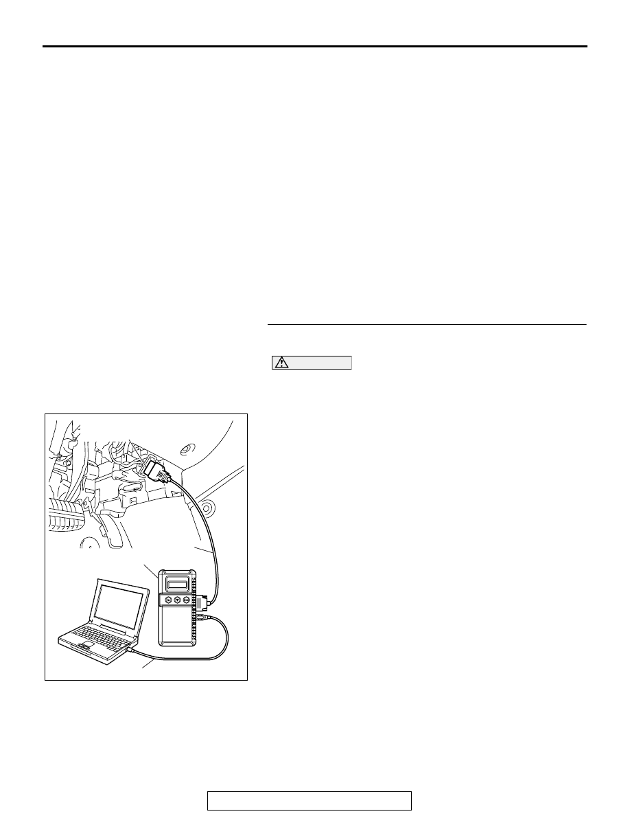
STEP 1. Using scan tool MB991958, diagnose the CAN bus 
line.

CAUTION

To prevent damage to scan tool MB991958, always turn the 
ignition switch to the "LOCK" (OFF) position before con-
necting or disconnecting scan tool MB991958.
(1) Connect scan tool MB991958. Refer to "How to connect the 

scan tool 

P.52B-30

."

(2) Turn the ignition switch to the "ON" position.
(3) Diagnose the CAN bus line.
(4) Turn the ignition switch to the "LOCK" (OFF) position.

Q: Is the CAN bus line found to be normal?

YES : Go to Step 2.
NO :  Repair the CAN bus line (Refer to GROUP 54C, 

Diagnosis ).

AC305412

AB

MB991910

DATA LINK

CONNECTOR

MB991824

MB991827

SRS AIR BAG DIAGNOSIS

TSB Revision

SUPPLEMENTAL RESTRAINT SYSTEM (SRS)

52B-79

STEP 2. Recheck for diagnostic trouble code.
Check again if the DTC is set.
(1) Erase the DTC.
(2) Turn the ignition switch to the "ON" position.
(3) Check if the DTC is set.
(4) Turn the ignition switch to the "LOCK" (OFF) position.

Q: Is the DTC set?

YES : Go to Step 3.
NO :  There is an intermittent malfunction such as poor 

engaged connector(s) or open circuit (Refer to 
GROUP 00, How to Use Troubleshooting/Inspection 
Service Points 

− How to Cope with Intermittent 

Malfunctions ).

STEP 3. Check for any diagnostic trouble code. (Using 
scan tool MB991958, read the diagnostic trouble code.)
Check the front impact sensor (RH).
(1) Disconnect the negative battery terminal.
(2) Replace the front impact sensor (RH) with the front impact 

sensor (LH).

(3) Connect the negative battery terminal.
(4) Erase diagnostic trouble code from memory, and check the 

diagnostic trouble code.

Q: Is DTC B1418 or B1419 set?

YES : Replace the front impact sensor (RH) with a new one 

(Refer to 

P.52B-377

). Then go to Step 5.

NO :  Go to Step 4.

AC305412

AB

MB991910

DATA LINK

CONNECTOR

MB991824

MB991827

AC305412

AB

MB991910

DATA LINK

CONNECTOR

MB991824

MB991827

SRS AIR BAG DIAGNOSIS

TSB Revision

SUPPLEMENTAL RESTRAINT SYSTEM (SRS)

52B-80

STEP 4. Check the harness wires for open circuit or short 
circuit between SRS-ECU connector C-121 (terminal No.47 
and 48) and front impact sensor (RH) connector A-27 
(terminal No.1 and 2).

NOTE: After inspecting intermediate connectors C-22 and C-11 
inspect the wiring harness. If the intermediate connectors C-22 
and C-11 are damaged, repair or replace it.

Q: Are the harness wires between SRS-ECU connector 

C-121 (terminal No.47 and 48) and front impact sensor 
(RH) connector A-27 (terminal No.1 and 2) in good 
condition? 
YES : 
Erase the diagnostic trouble code memory, and check 

the diagnostic trouble code. If DTC B1408 or B1409 
sets, replace the SRS-ECU (Refer to 

P.52B-365

). 

Then go to Step 5.

NO :  Replace the harness wires between SRS-ECU 

connector C-121 and front impact sensor (RH) 
connector A-27. Then go to Step 5.

AC305362

CONNECTOR: C-121

C-121 (Y)

AH

SRS-ECU

C-121
HARNESS SIDE 
CONNECTOR
(REAR VIEW)

42

31

38

27

21

41

28

39

22

30

25

47

36

33

44

34

45

37

48

26

29

23

40

32

43

35

46

24

B

A

AC305206

A-27 (Y)

HARNESS SIDE

BA

CONNECTOR: A-27

AC305233 AI

CONNECTOR: C-22

C-22 (Y)

AC305233CN

CONNECTOR: C-11

SRS AIR BAG DIAGNOSIS

TSB Revision

SUPPLEMENTAL RESTRAINT SYSTEM (SRS)

52B-81

STEP 5. Recheck for diagnostic trouble code.
Check again if the DTC is set.
(1) Erase the DTC.
(2) Turn the ignition switch to the "ON" position.
(3) Check if the DTC is set.
(4) Turn the ignition switch to the "LOCK" (OFF) position.

Q: Is DTC B1408 or B1409 set?

YES : Return to Step 1.
NO :  The procedure is complete.

AC305412

AB

MB991910

DATA LINK

CONNECTOR

MB991824

MB991827


Content   ..  1415  1416  1417  1418   ..