Mitsubishi Galant 9G. Manual - part 1373


  Index      Mitsubishi     Mitsubishi Galant 9G - service repair manual


Search            


Content   ..  1371  1372  1373  1374   ..


Mitsubishi Galant 9G. Manual - part 1373


DIAGNOSIS

TSB Revision

CONTROLLER AREA NETWORK (CAN)

54C-596

TROUBLE JUDGMENT

If the MUT-III cannot received signals from the 
SRS-ECU, CAN bus line connector(s) are broken or 
an open circuit has occurred.

.

COMMENTS ON TROUBLE SYMPTOM

The wiring harness wire or connectors may have 
loose, corroded, or damage terminals, or terminals 
pushed back in the connector, or the SRS-ECU may 
be defective.

.

TROUBLESHOOTING HINTS

• The wiring harness or connectors may have 

loose, corroded, or damage terminals, or termi-
nals pushed back in the connector

• The SRS-ECU may be defective

DIAGNOSIS

Required Special Tool:

• MB991223: Harness Set

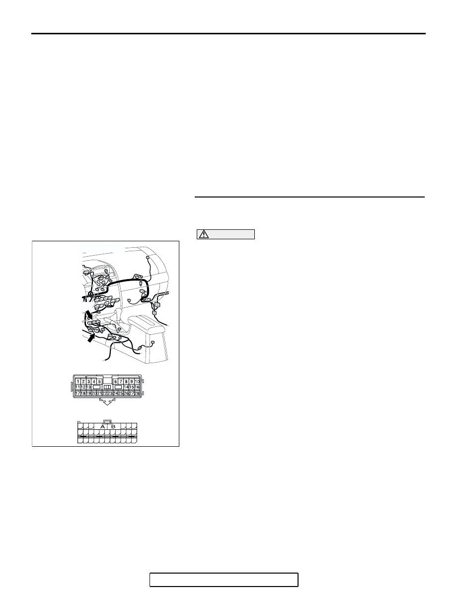
STEP 1. Check intermediate connector C-22 and SRS-ECU 
connector C-121 for loose, corroded or damaged 
terminals, or terminals pushed back in the connector.

CAUTION

The strand end of the twisted wire should be within 10 cm 
(4 inches) from the connector. For details refer to 

P.54C-4

.

Q: Are intermediate connector C-22 and SRS-ECU 

connector C-121 in  good condition?
YES : 
Go to Step 2.
NO :  Repair the damaged parts. Replace the joint 

connector as necessary.

AC305234AC

CONNECTORS: C-22, C-121

C-121 HARNESS SIDE

C-121 (Y)

C-22 (Y)

C-22

48

21

22

23

24

25

26

27

28

29

30

31

32

33

34

35

36

37

38

39

40

41

42

43

44

45

46

47

DIAGNOSIS

TSB Revision

CONTROLLER AREA NETWORK (CAN)

54C-597

STEP 2. Check the CAN bus lines between intermediate 
connector C-22 and the SRS-ECU. Measure the resistance 
between intermediate connector C-22 and SRS-ECU 
connector C-121.

CAUTION

A digital multimeter should be used. For details refer to 

P.54C-4

.

CAUTION

The test wiring harness should be used. For details refer to 

P.54C-4

.

(1) Disconnect intermediate connector C-22 and SRS-ECU 

connector C-121, and measure the resistance between the 
wiring harness side connector of SRS-ECU connector 
C-121 and the male side connector of intermediate 
connector C-22 (at front wiring harness side).

(2) Turn the ignition switch to the "LOCK" (OFF) position.

CAUTION

Disconnect the negative battery terminal. For details refer 
to 

P.54C-4

.

(3) Disconnect the negative battery terminal.

AC305234AC

CONNECTORS: C-22, C-121

C-121 HARNESS SIDE

C-121 (Y)

C-22 (Y)

C-22

48

21

22

23

24

25

26

27

28

29

30

31

32

33

34

35

36

37

38

39

40

41

42

43

44

45

46

47

DIAGNOSIS

TSB Revision

CONTROLLER AREA NETWORK (CAN)

54C-598

(4) Measure the resistance between intermediate connector 

terminal 23 and SRS-ECU connector terminal 43.

OK: 2 ohms or less

(5) Measure the resistance between intermediate connector 

terminal 22 and SRS-ECU connector terminal 32.

OK: 2 ohms or less

CAUTION

Strictly observe the specified wiring harness repair proce-
dure. For details refer to 

P.54C-5

.

Q: Do all the resistances measure 2 ohms or less?

YES : If all the resistances measure 2 ohms or less, go to 

Step 3.

NO :  If either of the resistances measures more than 2 

ohms or all the resistances measure more than 2 
ohms, repair the wiring harness between intermediate 
connector C-22 and the SRS-ECU connector. 

AC204582

48

21

22

23

24

25

26

27

28

29

30

31

32

33

34

35

36

37

38

39

40

41

42

43

44

45

46

47

AC204582

TEST 
HARNESS

CB

TEST 
HARNESS

MALE SIDE: C-22

HARNESS SIDE: C-121

AC204582

48

21

22

23

24

25

26

27

28

29

30

31

32

33

34

35

36

37

38

39

40

41

42

43

44

45

46

47

AC204582

TEST 
HARNESS

CC

TEST 
HARNESS

MALE SIDE: C-22

HARNESS SIDE: C-121

DIAGNOSIS

TSB Revision

CONTROLLER AREA NETWORK (CAN)

54C-599

STEP 3. Check joint connector (3) C-02 for loose, corroded 
or damaged terminals, or terminals pushed back in the 
connector.

CAUTION

The strand end of the twisted wire should be within 10 cm 
(4 inches) from the connector. For details refer to 

P.54C-4

.

Check the joint connector at the wiring harness side for loose, 
corroded or damaged terminals, or terminals pushed back in 
the connector, and also check the short pin behind the connec-
tor for corrosion, deformation and delamination.
Q: Is joint connector (3) C-02  in good condition?

YES : Go to Step 4.
NO :  Repair the damaged parts. Replace the joint 

connector as necessary.

AC305231AP

CONNECTOR: C-02

AC209350

1

12

2

13

3

14

4

15

5

16

6

17

7

18

8

19

9

20

10

21

11

22

AB

SHORT PIN


Content   ..  1371  1372  1373  1374   ..