Mitsubishi Galant 9G. Manual - part 1347


  Index      Mitsubishi     Mitsubishi Galant 9G - service repair manual


Search            


Content   ..  1345  1346  1347  1348   ..


Mitsubishi Galant 9G. Manual - part 1347


DIAGNOSIS

TSB Revision

CONTROLLER AREA NETWORK (CAN)

54C-492

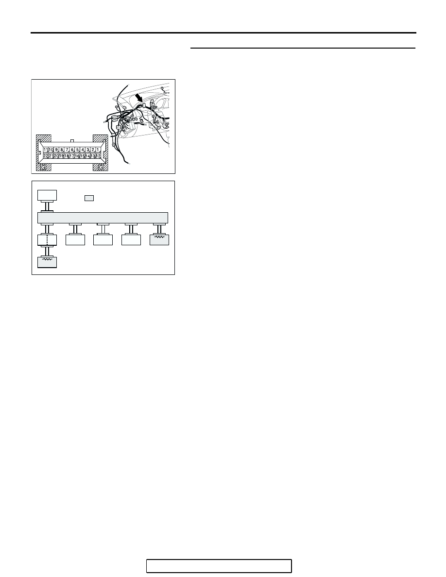
STEP 6. Using scan tool MB991958, diagnose the CAN bus 
line (Disconnect combination meter connector C-101, and 
check the combination meter system).
(1) Disconnect combination meter connector C-101.
(2) Turn the ignition switch to the "ON" position.

(3) Diagnose CAN bus lines, and check if the MUT-III screen is 

as shown in the illustration.

(4) Turn the ignition switch to the "LOCK" (OFF) position.
(5) Disconnect combination meter connector C-101.
Q: Does the MUT-III screen correspond to the illustration?

YES : If the MUT-III screen corresponds to the illustration, 

go to Step 7.

NO :  If the MUT-III screen does not correspond to the 

illustration, go to Step 8.

AC305231AQ

CONNECTOR: C-101

HARNESS SIDE

AC306074

: Red section on screen

AC

PCM

METER

-ECU

MUT

ETACS

-ECU

AC-ECU

SRS-ECU

ABS-ECU

J/C

DIAGNOSIS

TSB Revision

CONTROLLER AREA NETWORK (CAN)

54C-493

STEP 7. Check the CAN bus lines between joint connector 
(3) and the combination meter. Measure the resistance 
between joint connector (3) C-02 and combination meter 
connector C-101.

CAUTION

A digital multimeter should be used. For details refer to 

P.54C-4

.

CAUTION

The test wiring harness should be used. For details refer to 

P.54C-4

.

(1) Disconnect joint connector (3) C-02 and combination meter 

connector C-101, and measure the resistance between 
each wiring harness side connector.

(2) Turn the ignition switch to the "LOCK" (OFF) position.

CAUTION

Disconnect the negative battery terminal. For details refer 
to 

P.54C-4

.

(3) Disconnect the negative battery terminal.

AC305232

HARNESS SIDE

C-101

CONNECTORS: C-02, C-101

AE

C-02

C-02

C-101

DIAGNOSIS

TSB Revision

CONTROLLER AREA NETWORK (CAN)

54C-494

(4) Measure the resistance between joint connector (3) 

terminal 15 and combination meter connector terminal 15.

OK: 2 ohms or less

(5) Measure the resistance between joint connector (3) 

terminal 4 and combination meter connector terminal 14.

OK: 2 ohms or less

CAUTION

Strictly observe the specified wiring harness repair proce-
dure. For details refer to 

P.54C-5

.

Q: Do all the resistances measure 2 ohms or less?

YES : If all the resistances measure 2 ohms or less, power 

supply to the combination meter may be suspected. 
Diagnose the combination meter by referring to 
GROUP 54A, Combination meter assembly 

P.54A-252

.

NO :  If either of the resistances measures more than 2 

ohms or all the resistances measure more than 2 
ohms, repair the wiring harness between joint 
connector (3) and the combination meter connector. 

AC204582

HARNESS SIDE: C-02

BZ

11

22

10

21

9

20

8

19

7

18

6

17

5

16

4

15

3

14

2

13

1

12

G

G

22

11

5

16

19

20

21

17

18

8

10 9

7 6

13

1514

12

2

4 3

1

TEST 
HARNESS

HARNESS SIDE: C-101

TEST 
HARNESS

AC204582

HARNESS SIDE: C-02

TEST 
HARNESS

11

22

10

21

9

20

8

19

7

18

6

17

5

16

4

15

3

14

2

13

1

12

G

G

22

11

5

16

19

20

21

17

18

8

10 9

7 6

13

1514

12

2

4 3

1

TEST 
HARNESS

HARNESS SIDE: C-101

CA

DIAGNOSIS

TSB Revision

CONTROLLER AREA NETWORK (CAN)

54C-495

STEP 8. Check ETACS-ECU connector C-218 for loose, 
corroded or damaged terminals, or terminals pushed back 
in the connector.

CAUTION

The strand end of the twisted wire should be within 10 cm 
(4 inches) from the connector. For details refer to 

P.54C-4

.

Q: Is ETACS-ECU connector C-218 in good condition?

YES : Go to Step 9.
NO :  Repair the damaged parts.

STEP 9. Using scan tool MB991958, diagnose the CAN bus 
line (Disconnect ETACS-ECU connector C-218, and check 
the ETACS-ECU system).
(1) Disconnect ETACS-ECU connector C-218.
(2) Turn the ignition switch to the "ON" position.

(3) Diagnose CAN bus lines, and check if the MUT-III screen is 

as shown in the illustration.

(4) Turn the ignition switch to the "LOCK" (OFF) position.
(5) Connect ETACS-ECU connector C-218.
Q: Does the MUT-III screen correspond to the illustration?

YES : If the MUT-III screen corresponds to the illustration, 

go to Step 10 .

NO :  If the MUT-III screen does not correspond to the 

illustration, go to Step 11.

AC305413

C-218 (GR)

CONNECTOR: C-218

AI

HARNESS SIDE

JUNCTION BLOCK
(REAR VIEW)

68

74

63

66

72

73

67

65 64

61

70

71

62

69

60

57

58

59

56 55

52

54 53

51

AC305413

C-218 (GR)

CONNECTOR: C-218

AI

HARNESS SIDE

JUNCTION BLOCK
(REAR VIEW)

68

74

63

66

72

73

67

65 64

61

70

71

62

69

60

57

58

59

56 55

52

54 53

51

AC306074

: Red section on screen

AD

MUT

ETACS

-ECU

AC-ECU

SRS-ECU

ABS-ECU

J/C

METER

-ECU

PCM


Content   ..  1345  1346  1347  1348   ..