Mitsubishi Galant 9G. Manual - part 1343


  Index      Mitsubishi     Mitsubishi Galant 9G - service repair manual


Search            


Content   ..  1341  1342  1343  1344   ..


Mitsubishi Galant 9G. Manual - part 1343


DIAGNOSIS

TSB Revision

CONTROLLER AREA NETWORK (CAN)

54C-476

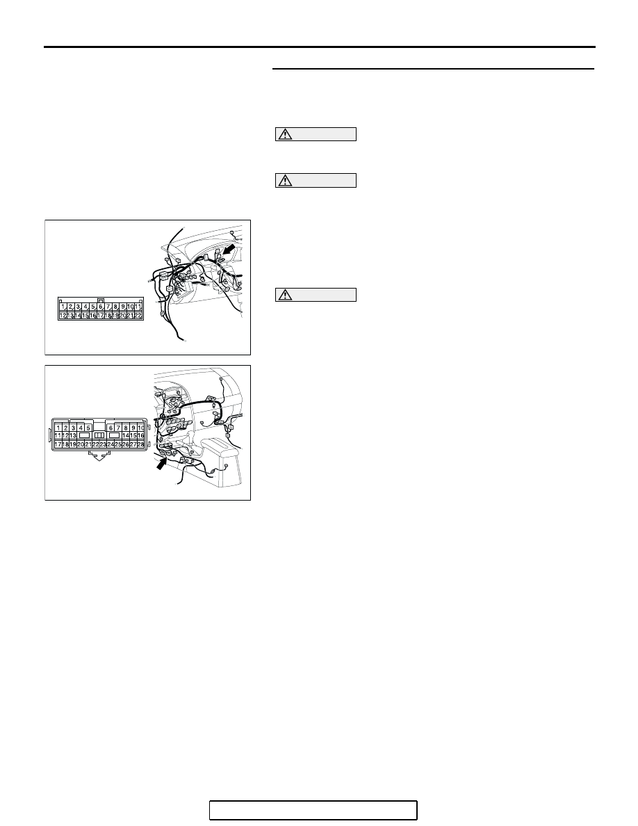
STEP 18. Check the CAN bus lines between joint 
connector (3) and the intermediate connector. Measure the 
resistance between joint connector (3) C-02 and 
intermediate connector C-22.

CAUTION

A digital multimeter should be used. For details refer to 

P.54C-4

.

CAUTION

The test wiring harness should be used. For details refer to 

P.54C-4

.

(1) Disconnect joint connector (3) C-02 and intermediate 

connector C-22, and measure the resistance at the wiring 
harness sides of joint connector (3) C-02 and intermediate 
connector C-22.

(2) Turn the ignition switch to the "LOCK" (OFF) position.

CAUTION

Disconnect the negative battery terminal. For details refer 
to 

P.54C-4

.

(3) Disconnect the negative battery terminal.

AC305231AP

CONNECTOR: C-02

AC305233 AI

CONNECTOR: C-22

C-22 (Y)

DIAGNOSIS

TSB Revision

CONTROLLER AREA NETWORK (CAN)

54C-477

(4) Measure the resistance between joint connector (3) 

terminal 3 and intermediate connector terminal 22.

OK: 2 ohms or less

(5) Measure the resistance between joint connector (3) 

terminal 14 and intermediate connector terminal 23.

OK: 2 ohms or less

CAUTION

Strictly observe the specified wiring harness repair proce-
dure. For details refer to 

P.54C-5

.

Q: Do all the resistances measure 2 ohms or less?

YES  : If all the resistances measure 2 ohms or less, power 

supply to the SRS-ECU may be suspected. Diagnose 
the supplemental restraint system. Refer to GROUP 
52B, SRS air bag diagnosis, equipment diagnosis 

P.52B-29

.

NO  : If either of the resistances measures more than 2 

ohms or all the resistances measure more than 2 
ohms, repair the wiring harness between joint 
connector (3) and the intermediate connector. 

AC204582

AC204582

HARNESS SIDE: C-02

TEST 
HARNESS

CE

11

22

10

21

9

20

8

19

7

18

6

17

5

16

4

15

3

14

2

13

1

12

TEST 
HARNESS

FEMALE SIDE: C-22

AC204582

AC204582

11

22

10

21

9

20

8

19

7

18

6

17

5

16

4

15

3

14

2

13

1

12

TEST 
HARNESS

CD

TEST 
HARNESS

HARNESS SIDE: C-02

FEMALE SIDE: C-22

DIAGNOSIS

TSB Revision

CONTROLLER AREA NETWORK (CAN)

54C-478

STEP 19. Check the CAN bus lines between joint 
connector (3) and the data link connector. Measure the 
resistance between joint connector (3) C-02 and data link 
connector C-125.

CAUTION

A digital multimeter should be used. For details refer to 

P.54C-4

.

CAUTION

The test wiring harness should be used. For details refer to 

P.54C-4

.

(1) Disconnect joint connector (3) C-02, and measure the 

resistance between the wiring harness side connector of 
joint connector (3) C-02 and wiring harness side connector 
of data link connector C-125.

(2) Turn the ignition switch to the "LOCK" (OFF) position.

CAUTION

Disconnect the negative battery terminal. For details refer 
to 

P.54C-4

.

(3) Disconnect the negative battery terminal.

AC305232

C-125

CONNECTORS: C-02, C-125

AF

C-02

C-02

C-125 (B)

DIAGNOSIS

TSB Revision

CONTROLLER AREA NETWORK (CAN)

54C-479

(4) Measure the resistance between joint connector (3) 

terminal 18 and data link connector terminal 14.

OK: 2 ohms or less

(5) Measure the resistance between joint connector (3) 

terminal 7 and data link connector terminal 6.

OK: 2 ohms or less

CAUTION

Strictly observe the specified wiring harness repair proce-
dure. For details refer to 

P.54C-5

.

Q: Do all the resistances measure 2 ohms or less?

YES  : If all the resistances measure 2 ohms or less, refer to 

diagnostics item 7: Check the CAN_L and H lines for 
a short circuit (Refer to 

P.54C-304

).

NO :  If all the resistances measure 2 ohms or less, repair 

the wiring harness between joint connector (3) and 
the data link connector.

AC204582DI

11

22

10

21

9

20

8

19

7

18

6

17

5

16

4

15

3

14

2

13

1

12

TEST 
HARNESS

HARNESS SIDE: C-02

TEST 
HARNESS

Y

8

16

15

7

5

1314

6

12

4

2

1011

3

9

1

HARNESS SIDE: C-125

AC204582

HARNESS SIDE: C-02

TEST 
HARNESS

DH

11

22

10

21

9

20

8

19

7

18

6

17

5

16

4

15

3

14

2

13

1

12

Y

8

16

15

7

5

1314

6

12

4

2

1011

3

9

1

TEST 
HARNESS

HARNESS SIDE: C-125


Content   ..  1341  1342  1343  1344   ..