Mitsubishi Galant 9G. Manual - part 1334


  Index      Mitsubishi     Mitsubishi Galant 9G - service repair manual


Search            


Content   ..  1332  1333  1334  1335   ..


Mitsubishi Galant 9G. Manual - part 1334


DIAGNOSIS

TSB Revision

CONTROLLER AREA NETWORK (CAN)

54C-440

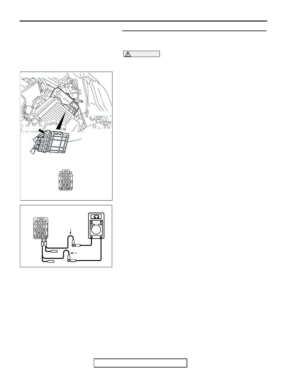
STEP 9. Check the terminator resistor inside the 
powertrain control module. Measure the resistance at 
powertrain control module connector B-19.

CAUTION

A digital multimeter should be used. For details refer to 

P.54C-4

.

(1) Disconnect powertrain control module connector B-19, and 

measure the resistance at the component side of 
powertrain control module connector B-19.

(2) Measure the resistance between powertrain control module 

connector terminals 17 and 18.

OK: 120 

± 20 

Q: Does the resistance measure 120 

± 20 ?

YES : If the resistance measures 120 

± 20 Ω, diagnose CAN 

bus lines thoroughly by referring to 

P.54C-456

.

NO :  If the resistance does not measure 120 

± 20 , replace 

the powertrain control module.

AC306248AD

B-19 (B)

CONNECTOR: B-19

PCM

AIR
CLEANER

HARNESS SIDE

AC209438

AC209438

AC209438

AC209438

COMPONENT SIDE: B-19

BD

TEST 
HARNESS

TEST 
HARNESS

DIAGNOSIS

TSB Revision

CONTROLLER AREA NETWORK (CAN)

54C-441

DIAGNOSTIC ITEM 13: Diagnose a terminator resistor at either end <Vehicles with ABS>

CAUTION

When servicing a CAN bus line, ground yourself 
by touching a metal object such as an unpainted 
water pipe. If you fail to do so, a component con-
nected to the CAN bus line may be damaged.

POWERTRAIN
CONTROL MODULE

ABS-ECU

JOINT
CONNECTOR (3)

COMBINATION
METER

DIAGNOSIS

TSB Revision

CONTROLLER AREA NETWORK (CAN)

54C-442

.

TROUBLE JUDGMENT

A terminator resistor at either end (including the CAN 
bus lines) may be damaged, when the resistance 
between the CAN bus lines (CAN_L and H lines) is 
120 

± 20 Ω.

.

COMMENTS ON TROUBLE SYMPTOM

The CAN bus line harness wires or connectors may 
be damaged or the combination meter or the power-
train control module may be defective.

.

TROUBLESHOOTING HINTS

• The wiring harness or connectors may have 

loose, corroded, or damage terminals, or termi-
nals pushed back in the connector

• The combination meter may be defective

• The ABS-ECU may be defective

• The powertrain control module may be defective

AC305206

CONNECTOR: A-02

AR

A-02 (GR)

AC306248AB

B-19 (B)

CONNECTOR: B-19

AIR
CLEANER

PCM

AC305231CA

C-101

C-29

C-02

CONNECTORS: C-02, C-29, C-101

DIAGNOSIS

TSB Revision

CONTROLLER AREA NETWORK (CAN)

54C-443

DIAGNOSIS

Required Special Tools:

• MB991223: Harness Set

• MB991970: ABS Check Harness

STEP 1. Check intermediate connector C-29 for loose, 
corroded or damaged terminals, or terminals pushed back 
in the connector.

CAUTION

The strand end of the twisted wire should be within 10 cm 
(4 inches) from the connector. For details refer to 

P.54C-4

.

Q: Is intermediate connector C-29 in good condition?

YES : Go to Step 2.
NO :  Repair the damaged parts.

AC305231AI

CONNECTOR: C-29


Content   ..  1332  1333  1334  1335   ..