Content .. 1322 1323 1324 1325 ..
Mitsubishi Galant 9G. Manual - part 1324
DIAGNOSIS
TSB Revision
CONTROLLER AREA NETWORK (CAN)
54C-400
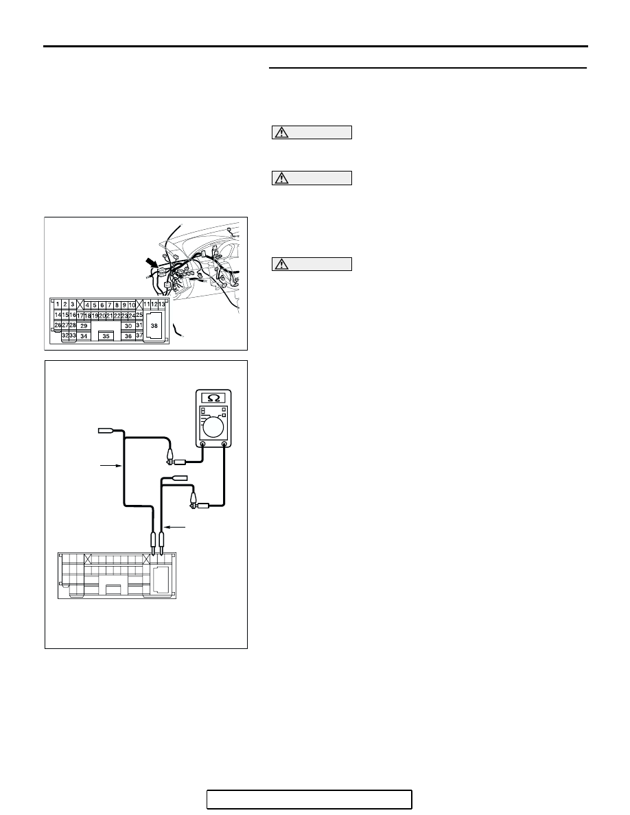
STEP 8. Check the front wiring harness side CAN bus lines
(communication line including the powertrain control
module). Measure the resistance at intermediate connector
C-29.
CAUTION
A digital multimeter should be used. For details refer to
.
CAUTION
The test wiring harness should be used. For details refer to
.
(1) Disconnect intermediate connector C-29, and measure the
resistance at the male side (at front wiring harness side).
(2) Turn the ignition switch to the "LOCK" (OFF) position.
CAUTION
Disconnect the negative battery terminal. For details refer
to
(3) Disconnect the negative battery terminal.
(4) Measure the resistance between intermediate connector
terminals 11 and 12.
OK: 120
± 20 Ω
Q: Does the resistance measure 120
± 20 Ω?
YES : If the resistance measures 120
± 20 Ω, go to Step 12.
NO : If the resistance does not measure 120
± 20 Ω, go to
Step 9 .
AC305231AI
CONNECTOR: C-29
AC204582
2 3
27
32
28
33
16
15
4 5
19
18
29
17
34
7 8
35
22
21
9 10
30
36
31
37
25
24
23
6
20
1
14
26
11
13
12
38
BX
TEST
HARNESS
TEST
HARNESS
MALE SIDE: C-29