Mitsubishi Galant 9G. Manual - part 1309


  Index      Mitsubishi     Mitsubishi Galant 9G - service repair manual


Search            


Content   ..  1307  1308  1309  1310   ..


Mitsubishi Galant 9G. Manual - part 1309


DIAGNOSIS

TSB Revision

CONTROLLER AREA NETWORK (CAN)

54C-340

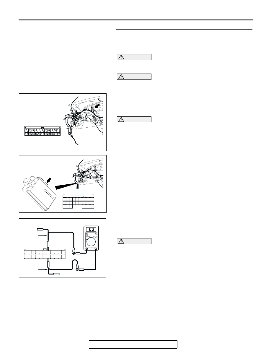
STEP 10. Check the CAN_L and H lines (communication 
lines only) between joint connector (3) and the 
ETACS-ECU for a short circuit. Measure the resistance at 
joint connector (3) C-02.

CAUTION

A digital multimeter should be used. For details refer to 

P.54C-4

.

CAUTION

The test wiring harness should be used. For details refer to 

P.54C-4

.

(1) Disconnect joint connector (3) C-02 and ETACS-ECU 

connector C-218, and measure the resistance at the wiring 
harness side of joint connector (3) C-02.

(2) Turn the ignition switch to the "LOCK" (OFF) position.

CAUTION

Disconnect the negative battery terminal. For details refer 
to 

P.54C-4

.

(3) Disconnect the negative battery terminal.

(4) Measure the resistance between joint connector (3) 

terminals 5 and 16.

OK: 1 k

 or more

CAUTION

Strictly observe the specified wiring harness repair proce-
dure. For details refer to 

P.54C-5

.

Q: Does the resistance measure 1 k

 or more?

YES : If the resistance measures 1 k

Ω or more, go to Step 

11  .

NO :  If the resistance measures less than 1 k

Ω, repair the 

wiring harness between joint connector (3) and the 
ETACS-ECU connector.

AC305231AP

CONNECTOR: C-02

AC305413

C-218 (GR)

CONNECTOR: C-218

AI

HARNESS SIDE

JUNCTION BLOCK
(REAR VIEW)

68

74

63

66

72

73

67

65 64

61

70

71

62

69

60

57

58

59

56 55

52

54 53

51

AC209438

TEST 
HARNESS

AR

TEST 
HARNESS

11

22

10

21

9

20

8

19

7

18

6

17

5

16

4

15

3

14

2

13

1

12

HARNESS SIDE: C-02

DIAGNOSIS

TSB Revision

CONTROLLER AREA NETWORK (CAN)

54C-341

STEP 11. Check the ETACS-ECU for short circuit. Measure 
the resistance at ETACS-ECU connector C-218.

CAUTION

A digital multimeter should be used. For details refer to 

P.54C-4

.

(1) Disconnect ETACS-ECU connector C-218, and measure 

the resistance at the component side of ETACS-ECU 
connector C-218.

(2) Measure the resistance between ETACS-ECU connector 

terminals 72 and 73.

OK: 1 k

 or more

Q: Does the resistance measure 1 k

 or more?

YES : If the resistance measures 1 k

Ω or more, diagnose 

CAN bus lines thoroughly by referring to 

P.54C-486

.

NO :  If the resistance measures less than 1 k

Ω, replace the 

ETACS-ECU.

AC305413

C-218 (GR)

CONNECTOR: C-218

AI

HARNESS SIDE

JUNCTION BLOCK
(REAR VIEW)

68

74

63

66

72

73

67

65 64

61

70

71

62

69

60

57

58

59

56 55

52

54 53

51

AC209438

COMPONENT SIDE: C-218

AO

TEST 
HARNESS

5859

74

68

57

56

72

656667

73

54

63

52

70

61

53

62

71

64

55

51

60

69

TEST 
HARNESS

DIAGNOSIS

TSB Revision

CONTROLLER AREA NETWORK (CAN)

54C-342

STEP 12. Check the CAN_L and H lines (communication 
lines including the A/C-ECU) between joint connector (3) 
and the A/C-ECU for a short circuit. Measure the resistance 
at joint connector (3) C-02.

CAUTION

A digital multimeter should be used. For details refer to 

P.54C-4

.

CAUTION

The test wiring harness should be used. For details refer to 

P.54C-4

.

(1) Disconnect joint connector (3) C-02, and measure the 

resistance at the wiring harness side of joint connector (3) 
C-02.

(2) Turn the ignition switch to the "LOCK" (OFF) position.

CAUTION

Disconnect the negative battery terminal. For details refer 
to 

P.54C-4

.

(3) Disconnect the negative battery terminal.

(4) Measure the resistance between joint connector (3) 

terminals 6 and 17.

OK: 1 k

 or more

Q: Does the resistance measure 1 k

 or more?

YES : If the resistance measures 1 k

Ω or more, go to Step 

16  .

NO :  If the resistance measures less than 1 k

Ω, go to Step 

13.

AC305231AP

CONNECTOR: C-02

AC209438

AC209438

TEST 
HARNESS

AS

TEST 
HARNESS

1110 9 8 7 6 5 4 3 2 1

22 21201918 1716 15 14 1312

HARNESS SIDE: C-02

DIAGNOSIS

TSB Revision

CONTROLLER AREA NETWORK (CAN)

54C-343

STEP 13. Check A/C-ECU connector C-10 <manual air 
conditioning system (low)> or C-15 <manual air 
conditioning system (middle) or automatic air conditioning 
system> for loose, corroded or damaged terminals, or 
terminals pushed back in the connector.

CAUTION

The strand end of the twisted wire should be within 10 cm 
(4 inches) from the connector. For details refer to 

P.54C-4

.

Q: Is A/C-ECU connector C-10 <manual air conditioning 

system (low)> or C-15 <manual air conditioning system 
(middle) or automatic air conditioning system> in good 
condition?
YES : 
Go to Step 14.
NO :  Repair the damaged parts.

AC305234AB

C-10 HARNESS SIDE

C-15 HARNESS SIDE

CONNECTORS: C-10, C-15

C-10 (B)

C-15 (B)


Content   ..  1307  1308  1309  1310   ..