Content .. 1302 1303 1304 1305 ..
Mitsubishi Galant 9G. Manual - part 1304
DIAGNOSIS
TSB Revision
CONTROLLER AREA NETWORK (CAN)
54C-320
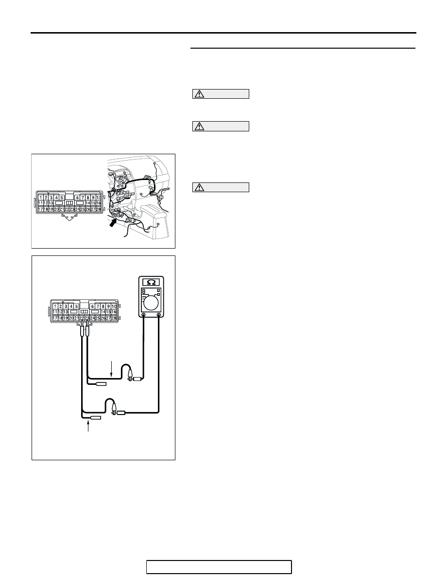
STEP 18. Check the lines between the CAN_L and H lines
(communication line including ECUs) of the floor wiring
harness for a short circuit. Measure the resistance at
intermediate connector C-22.
CAUTION
A digital multimeter should be used. For details refer to
.
CAUTION
The test wiring harness should be used. For details refer to
.
(1) Disconnect intermediate connector C-22, and measure the
resistance at the male side (at floor wiring harness side).
(2) Turn the ignition switch to the "LOCK" (OFF) position.
CAUTION
Disconnect the negative battery terminal. For details refer
to
(3) Disconnect the negative battery terminal.
(4) Measure the resistance between intermediate connector
terminals 22 and 23.
OK: 120
± 20 Ω
Q: Does the resistance measure 120
± 20 Ω?
YES : If the resistance measures 120
± 20 Ω, go to Step 22.
NO : If the resistance does not measure 120
± 20 Ω> Go to
Step 19.
AC305233 AI
CONNECTOR: C-22
C-22 (Y)
AC204582
AC204582CS
MALE SIDE: C-22
TEST
HARNESS
TEST HARNESS