Content .. 1272 1273 1274 1275 ..
Mitsubishi Galant 9G. Manual - part 1274
DIAGNOSIS
TSB Revision
CONTROLLER AREA NETWORK (CAN)
54C-200
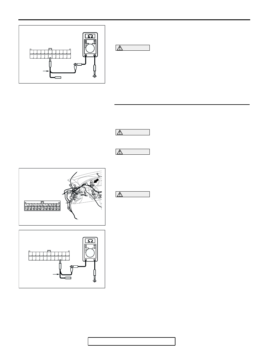
(4) Measure the resistance between joint connector (3)
terminal 17 and body ground.
OK: 1 k
Ω or more
CAUTION
Strictly observe the specified wiring harness repair proce-
dure. For details refer to
Q: Does the resistance measure 1 k
Ω or more?
YES : If the resistance measures 1 k
Ω or more, diagnose
CAN bus lines thoroughly by referring to
NO : If the resistance measures less than 1 k
Ω, repair the
wiring harness between joint connector (3) and the
A/C-ECU connector.
STEP 35. Check the CAN_L line (communication line
including the SRS-ECU) between joint connector (3) and
the SRS-ECU connector for short to ground. Measure the
resistance at joint connector (3) C-02.
CAUTION
A digital multimeter should be used. For details refer to
.
CAUTION
The test wiring harness should be used. For details refer to
.
(1) Disconnect joint connector (3) C-02, and measure the
resistance at the wiring harness side of joint connector (3)
C-02.
(2) Turn the ignition switch to the "LOCK" (OFF) position.
CAUTION
Disconnect the negative battery terminal. For details refer
to
(3) Disconnect the negative battery terminal.
(4) Measure the resistance between joint connector (3)
terminals 14 and body ground.
OK: 1 k
Ω or more
Q: Does the resistance measure 1 k
Ω or more?
YES : If the resistance measures 1 k
Ω or more, go to Step
NO : If the resistance measures less than 1 k
Ω, go to Step
AC209364
11
22
10
21
9
20
8
19
7
18
6
17
5
16
4
15
3
14
2
13
1
12
AC209364
AC209364HY
HARNESS SIDE: C-02
TEST
HARNESS
AC305231AP
CONNECTOR: C-02
AC209364IK
11
22
10
21
9
20
8
19
7
18
6
17
5
16
4
15
3
14
2
13
1
12
HARNESS SIDE: C-02
TEST
HARNESS