Content .. 1261 1262 1263 1264 ..
Mitsubishi Galant 9G. Manual - part 1263
DIAGNOSIS
TSB Revision
CONTROLLER AREA NETWORK (CAN)
54C-156
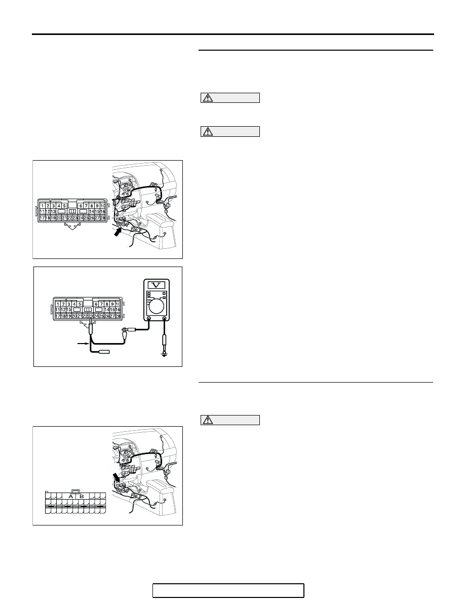
STEP 43. Check the CAN_L-side bus line (communication
line including ECUs) of the floor wiring harness for short
to the power supply. Measure the voltage at intermediate
connector C-22.
CAUTION
A digital multimeter should be used. For details refer to
.
CAUTION
The test wiring harness should be used. For details refer to
.
(1) Disconnect intermediate connector C-22, and measure the
voltage at the male side (at floor wiring harness side).
(2) Turn the ignition switch to the "ON" position.
(3) Measure the voltage between intermediate connector
terminal 23 and body ground.
OK: 4.0 V or less
Q: Does the voltage measure 4.0 V or less?
YES : If the voltage measures 4.0 V or less, go to Step 46.
NO : If the voltage measures more than 4.0 V, go to Step
STEP 44. Check SRS-ECU connector C-121 for loose,
corroded or damaged terminals, or terminals pushed back
in the connector.
CAUTION
The strand end of the twisted wire should be within 10 cm
(4 inches) from the connector. For details refer to
Q: Is SRS-ECU connector C-121 in good condition?
YES : Go to Step 45.
NO : Repair the damaged parts.
AC305233 AI
CONNECTOR: C-22
C-22 (Y)
AC209365
AC209365GF
MAIL SIDE: C-22
TEST
HARNESS
AC305233 AJ
CONNECTOR: C-121
HARNESS SIDE
C-121 (Y)
48
21
22
23
24
25
26
27
28
29
30
31
32
33
34
35
36
37
38
39
40
41
42
43
44
45
46
47