Mitsubishi Galant 9G. Manual - part 1237


  Index      Mitsubishi     Mitsubishi Galant 9G - service repair manual


Search            


Content   ..  1235  1236  1237  1238   ..


Mitsubishi Galant 9G. Manual - part 1237


DIAGNOSIS

TSB Revision

CONTROLLER AREA NETWORK (CAN)

54C-52

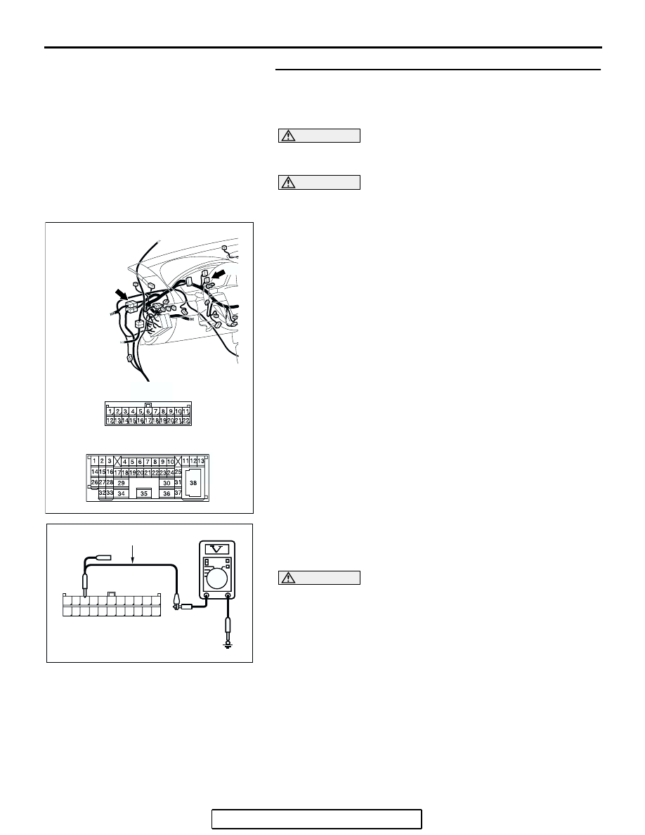
STEP 22. Check the CAN_H line (communication line only) 
between intermediate connector C-29 and joint connector 
(3) C-02 for a short to  the power supply. Measure the 
voltage at joint connector (3) C-02.

CAUTION

A digital multimeter should be used. For details refer to 

P.54C-4

.

CAUTION

The test wiring harness should be used. For details refer to 

P.54C-4

.

(1) Disconnect intermediate connector C-29 and joint 

connector (3) C-02, and measure the voltage at the wiring 
harness side of joint connector (3) C-02.

(2) Turn the ignition switch to the "ON" position.

(3) Measure the voltage between joint connector (3) terminal 9 

and body ground.

OK: 1.0 V or less

CAUTION

Strictly observe the specified wiring harness repair proce-
dure. For details refer to 

P.54C-5

.

Q: Does the voltage measure 1.0 V or less?

YES : If the voltage measures 1.0 V or less, diagnose CAN 

bus lines thoroughly by referring to 

P.54C-456

.

NO :  If the voltage measures more than 1.0 V, repair the 

wiring harness between intermediate connector and 
joint connector (3).

AC305232

CONNECTORS: C-02, C-29

AG

C-02

C-02

C-29

C-29

AC209365

11

22

10

21

9

20

8

19

7

18

6

17

5

16

4

15

3

14

2

13

1

12

AC209365FY

HARNESS SIDE: C-02

TEST HARNESS

DIAGNOSIS

TSB Revision

CONTROLLER AREA NETWORK (CAN)

54C-53

STEP 23. Check the CAN_H line (communication line only) 
between intermediate connector and the powertrain 
control module connector for a short circuit. Measure the 
voltage at intermediate connector C-29.

CAUTION

A digital multimeter should be used. For details refer to 

P.54C-4

.

CAUTION

The test wiring harness should be used. For details refer to 

P.54C-4

.

(1) Disconnect intermediate connector C-29 and powertrain 

control module connector B-19, and measure the voltage at 
the wiring harness side of intermediate connector C-29.

(2) Turn the ignition switch to the "ON" position.

AC306248AD

B-19 (B)

CONNECTOR: B-19

PCM

AIR
CLEANER

HARNESS SIDE

AC305231AI

CONNECTOR: C-29

DIAGNOSIS

TSB Revision

CONTROLLER AREA NETWORK (CAN)

54C-54

(3) Measure the voltage between intermediate connector 

terminal 11 and body ground.

OK: 1.0 V or less

CAUTION

Strictly observe the specified wiring harness repair proce-
dure. For details refer to 

P.54C-5

.

Q: Does the voltage measure 1.0 V or less?

YES : If the voltage measures 1.0 V or less, diagnose CAN 

bus lines thoroughly by referring to 

P.54C-456

.

NO :  If the voltage measures more than 1.0 V, repair the 

wiring harness between intermediate connector and 
the powertrain control module connector.

STEP 24. Check intermediate connector C-29 for loose, 
corroded or damaged terminals, or terminals pushed back 
in the connector.

CAUTION

The strand end of the twisted wire should be within 10 cm 
(4 inches) from the connector. For details refer to 

P.54C-4

.

Q: Is intermediate connector C-29 in good condition?

YES : Go to Step 25.
NO :  Repair the damaged parts.

AC209365

2 3

27

32

28

33

16

15

4 5

19

18

29

17

34

7 8

35

22

21

9 10

30

36

31

37

25

24

23

6

20

1

14

26

11

13

12

38

AC209365

MALE SIDE: C-29

TEST 
HARNESS

FP

AC305231AI

CONNECTOR: C-29

DIAGNOSIS

TSB Revision

CONTROLLER AREA NETWORK (CAN)

54C-55

STEP 25. Check the CAN_L-side bus line (communication 
line including) of the front wiring harness for a short to the 
power supply. Measure the voltage at intermediate 
connector C-29.

CAUTION

A digital multimeter should be used. For details refer to 

P.54C-4

.

CAUTION

The test wiring harness should be used. For details refer to 

P.54C-4

.

(1) Disconnect intermediate connector C-29, and measure the 

voltage at the male side (at front wiring harness side).

(2) Turn the ignition switch to the "ON" position.

(3) Measure the voltage between intermediate connector 

terminal 12 and body ground.

OK: 4.0 V or less

Q: Does the voltage measure 4.0 V or less?

YES : If the voltage measures 4.0 V or less, go to Step 26.
NO :  If the voltage measures more than 4.0 V, go to Step 

43.

AC305231AI

CONNECTOR: C-29

AC209365

2 3

27

32

28

33

16

15

4 5

19

18

29

17

34

7 8

35

22

21

9 10

30

36

31

37

25

24

23

6

20

1

14

26

11

13

12

38

AC209365

MALE SIDE: C-29

TEST HARNESS

GA


Content   ..  1235  1236  1237  1238   ..