Mitsubishi Galant 9G. Manual - part 1232


  Index      Mitsubishi     Mitsubishi Galant 9G - service repair manual


Search            


Content   ..  1230  1231  1232  1233   ..


Mitsubishi Galant 9G. Manual - part 1232


DIAGNOSIS

TSB Revision

CONTROLLER AREA NETWORK (CAN)

54C-32

.

TROUBLE JUDGMENT

A short to the power supply may be present when the 
voltage between the CAN bus line (CAN_L or 
CAN_H) and body ground is more than 4.0 V. In this 
condition, an abnormal voltage may be measured at 
CAN_L and CAN_H lines.

.

COMMENTS ON TROUBLE SYMPTOM

The wiring harness wire or connectors may have 
loose, corroded, or damage terminals, or terminals 
pushed back in the connector, or an ECU may be 
defective.

.

TROUBLESHOOTING HINTS

• The wiring harness or connectors may have 

loose, corroded, or damaged terminals, or termi-
nals pushed back in the connector

• The ETACS-ECU may be defective

• The combination meter may be defective

• The A/C-ECU may be defective

• The SRS-ECU may be defective

• The powertrain control module may be defective
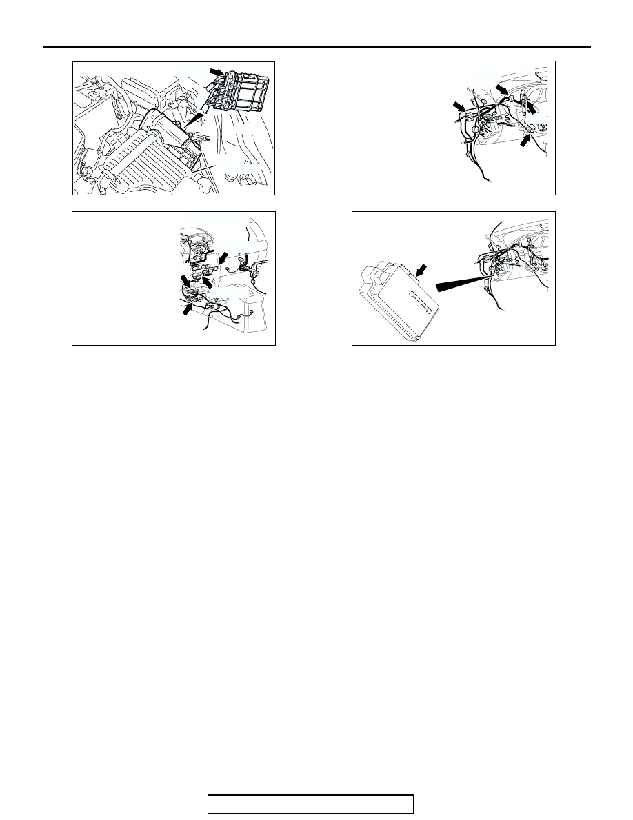
AC306248AB

B-19 (B)

CONNECTOR: B-19

AIR
CLEANER

PCM

AC305231BZ

C-101

C-125 (B)

C-29

C-02

CONNECTORS: C-02, C-29, C-101, C-125

AC305233 AU

CONNECTORS: C-10, C-15, C-22, C-121

C-121 (Y)

C-22 (Y)

C-10 (B)

C-15 (B)

AC305413

C-218 (GR)

CONNECTOR: C-218

AJ

JUNCTION BLOCK
(REAR VIEW)

DIAGNOSIS

TSB Revision

CONTROLLER AREA NETWORK (CAN)

54C-33

DIAGNOSIS

Required Special Tool:

• MB991223: Harness Set

STEP 1. Check powertrain control module connector B-19, 
combination meter connector C-101 and data link 
connector C-125 for loose, corroded or damaged 
terminals, or terminals pushed back in the connector.

CAUTION

The strand end of the twisted wire should be within 10 cm 
(4 inches) from the connector. For details refer to 

P.54C-4

.

Q: Are powertrain control module  connector B-19, 

combination meter connector C-101 and data link 
connector C-125 in  good condition?
YES : 
Go to Step 2.
NO :  Repair the damaged parts.

AC306248AD

B-19 (B)

CONNECTOR: B-19

PCM

AIR
CLEANER

HARNESS SIDE

AC305232

CONNECTORS: C-101, C-125

AH

C-101

C-125

C-125 (B)

C-101 HARNESS SIDE

DIAGNOSIS

TSB Revision

CONTROLLER AREA NETWORK (CAN)

54C-34

STEP 2. Check the CAN_H-side bus line (communication 
line including ECUs) for a short to the power supply. 
Measure the voltage at data link connector C-125.

CAUTION

A digital multimeter should be used. For details refer to 

P.54C-4

.

CAUTION

The test wiring harness should be used. For details refer to 

P.54C-4

.

(1) Disconnect powertrain control module connector B-19 and 

combination meter connector C-101, and measure the 
voltage at the harness side of data link connector C-125.

(2) Turn the ignition switch to the "ON" position.

AC306248AD

B-19 (B)

CONNECTOR: B-19

PCM

AIR
CLEANER

HARNESS SIDE

AC305232

CONNECTORS: C-101, C-125

AH

C-101

C-125

C-125 (B)

C-101 HARNESS SIDE

DIAGNOSIS

TSB Revision

CONTROLLER AREA NETWORK (CAN)

54C-35

(3) Measure the voltage between data link connector terminal 6 

and body ground.

OK: 4.0 V or less

Q: Does the voltage measure 4.0 V or less?

YES : If the voltage measures 4.0 V or less, go to Step 3.
NO :  If the voltage measures more than 4.0 V, go to Step 4.

AC209365

HARNESS SIDE: C-125

TEST 
HARNESS

FN

Y

8

16

15

7

5

1314

6

12

4

2

1011

3

9

1


Content   ..  1230  1231  1232  1233   ..