Content .. 1215 1216 1217 1218 ..
Mitsubishi Galant 9G. Manual - part 1217
MULTIPORT FUEL INJECTION (MFI) DIAGNOSIS
TSB Revision
MULTIPORT FUEL INJECTION (MFI) <3.8L ENGINE>
13B-1168
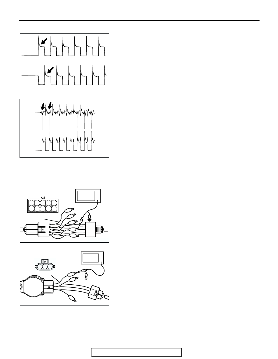
Examples of Abnormal Wave Patterns
Example 1
Cause of problem
• Malfunction of motor. (Motor is not operating.)
Wave pattern characteristics
• Induced electromotive force from the motor turning does
not appear.
Example 2
Cause of problem
• Open circuit in the line between the EGR valve and the
PCM.
Wave pattern characteristics
• Current is not supplied to the motor coil on the open cir-
cuit side. (Voltage does not drop to 0 volt.) Furthermore,
the induced electromotive force wave pattern at the nor-
mal side is slightly different from the normal wave pat-
tern.
IGNITION COIL AND IGNITION POWER
TRANSISTOR
Required Special Tools:
• MB991658: Test Harness
• MB991923: Power Plant ECU Check Harness
.
Measurement Method
<Measure at the right bank (number 1, 3, 5 cylinders)>
1. Disconnect the intermediate connector B-32, and connect
the test harness special tool (MB991658) between the sep-
arated connector.
2. Connect the oscilloscope probe to each intermediate con-
nector B-32 terminal to analyze each cylinder:
• Terminal No. 2 for the number 1 cylinder.
• Terminal No. 7 for the number 3 cylinder.
• Terminal No. 3 for the number 5 cylinder.
<Measure at the left bank (number 2, 4, 6 cylinders)>
1. Disconnect the ignition coil connector, and connect test har-
ness special tool (MB991658) between the separated con-
nector. (All terminals should be connected.)
2. Connect the oscilloscope probe to ignition coil connector
terminal No. 3.
.
AKX01608 AB
AKX01609
OPEN
CIRCUIT
SIDE
NORMAL
SIDE
AB
1
2 3
6
7 8
4 5
9 10
AK203305
OSCILLOSCOPE
MB991658
B-32 INTERMEDIATE
CONNECTOR
AB
AK401067
1 2 3
IGNITION COIL
CONNECTOR
OSCILLOSCOPE
MB991658
AB