Mitsubishi Galant 9G. Manual - part 1206


  Index      Mitsubishi     Mitsubishi Galant 9G - service repair manual


Search            


Content   ..  1204  1205  1206  1207   ..


Mitsubishi Galant 9G. Manual - part 1206


MULTIPORT FUEL INJECTION (MFI) DIAGNOSIS

TSB Revision

MULTIPORT FUEL INJECTION (MFI) <3.8L ENGINE>

13B-1124

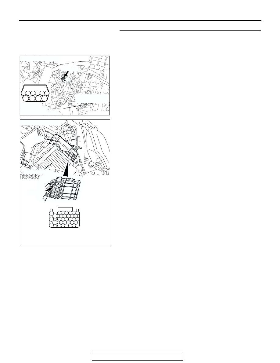
STEP 5. Check for open circuit and short circuit to ground 
and harness damage between transmission range switch 
connector B-110 (terminal No. 9) and PCM connector B-21 
(terminal No. 83).
Q: Is the harness wire in good condition?

YES : Replace the PCM. Then confirm that the malfunction 

symptom is eliminated.

NO :  Repair it. Then confirm that the malfunction symptom 

is eliminated.

8

9

3

4

5

1

2

6

7

10

AK303269AB

TRANSMISSION
RANGE SWITCH

CONNECTOR: B-110

B-110 (B)

HARNESS
CONNECTOR:
COMPONENT SIDE

AK303018

55

56

54 53 52 51

57

62 61 60 59 58

63

69 68 67 66 65 64

70

75 74 73 72 71

76

82 81 80 79 78 77

83

CONNECTOR: B-21

PCM

AB

HARNESS CONNECTOR: 
COMPONENT SIDE

AIR CLEANER

B-21 (B)

MULTIPORT FUEL INJECTION (MFI) DIAGNOSIS

TSB Revision

MULTIPORT FUEL INJECTION (MFI) <3.8L ENGINE>

13B-1125

INSPECTION PROCEDURE 31: Ignition Circuit System.

POWERTRAIN CONTROL MODULE (PCM)

B-111

(MU801215)

BLACK-
WHITE

SPARK
PLUG

IGNITION COIL

1 2 3

BLA

CK-

WHITE

BLUE-

BLA

C

K

PINK-

BLA

C

K

WHITE-

GREEN

CAPACITOR

1

B-23

121 122 123 124 125 126 127

128 129 130 131 132 133

134 135 136 137 138 139 140

141 142 143 144 145 146

147 148 149 150 151 152 153

BLA

CK-

WHITE

BLA

CK-

WHITE

BLA

CK-

WHITE

BLA

CK-

WHITE

6

IG2

ST

LOCK

ACC

IG1

2

IGNITION
SWITCH

R

15

11

10

3

4 5 6

1 2

C-308

Ignition Circuit

A-13

C-211

C-29

C-215

C-211

C-29

A-13

BLACK-
WHITE

C-215

(MU801331)

24

10A

1

6

4 5

11

10

1213

15

17

16

14

19

18

8 9

7

20

2 3

2122 23 24 25 26 27 28

1 2

3 4 5

14

15

8 9

12 13

6 7

10 11
16 17

1

2

3 4 5 6

B-103

GRA

Y

LIGHTGREEN

BLA

C

K

BLA

CK-

WHITE

IGNITION
COIL 5

1

3

2

BLA

C

K

6

3

7

2

1

134

148

150

151

144

143

B-32

MU802645

IGNITION COIL

CONNECTOR

MU802064

1

2 3

6

7 8

4

5

9 10

1

3

2

B-102

BLA

C

K

BLA

CK-

WHITE

IGNITION
COIL 3

1

3

2

BLA

CK-BLUE

B-101

BLA

C

K

BLA

CK-

WHITE

IGNITION
COIL 1

1

3

2

B-118

BLA

C

K

BLA

CK-

WHITE

IGNITION
COIL 2

1

3

2

B-117

BLA

C

K

BLA

CK-

WHITE

IGNITION
COIL 4

1

3

2

B-114

BLA

C

K

BLA

CK-

WHITE

IGNITION
COIL 6

1

3

2

1

AK400838

MULTIPORT FUEL INJECTION (MFI) DIAGNOSIS

TSB Revision

MULTIPORT FUEL INJECTION (MFI) <3.8L ENGINE>

13B-1126

.

AK303271AB

B-118 (GR)

B-102 (GR)

B-101 (GR)

B-117 (GR)

B-103 (GR)

B-114 (GR)

CONNECTOR: B-101, B-102, B-103, B-114,
                         B-117, B-118

AK303059

CONNECTOR: B-23

PCM

AB

AIR CLEANER

B-23

AK303227

CONNECTOR: C-211

C-211

AB

JUNCTION
BLOCK

AK203191

CONNECTOR: C-308

C-308

AB

AK303244

CONNECTOR: C-215

AB

JUNCTION
BLOCK

C-215

AK303231

CONNECTOR: C-29

C-29

AB

AK303148

CONNECTOR: A-13

AB

A-13(GR)

AK303097

CONNECTOR: B-32

AB

B-32 (B)

AK303272AB

B-111 (B)

CONNECTOR: B-111

MULTIPORT FUEL INJECTION (MFI) DIAGNOSIS

TSB Revision

MULTIPORT FUEL INJECTION (MFI) <3.8L ENGINE>

13B-1127

CIRCUIT OPERATION

• The ignition coil is energized by battery positive 

voltage from the ignition switch.

• When the PCM turns off its internal power tran-

sistor, battery positive voltage is applied to the 
ignition power transistor (terminal No. 3) inside 
the ignition coil, causing the ignition power tran-
sistor to be turned on.

• If the ignition power transistor is turned on, the 

primary circuit of the ignition coil is energized by 
grounding the ignition coil through terminal No. 2, 
causing the primary current to flow to the ignition 
coil.

.

TROUBLESHOOTING HINTS (The most 
likely causes for this case:)

• Malfunction of the ignition coil.

• Malfunction of the ignition power transistor.

• Improper connector contact, open circuit or 

short-circuit harness wire.

• Malfunction of the PCM.

DIAGNOSIS

STEP 1. Check the ignition coil.
(1) Remove the intake manifold.
(2) Refer to GROUP 16, Ignition System 

− On-vehicle service − 

Ignition Coil Check 

P.16-38

.

Q: Are there any abnormalities?

YES : Replace the ignition coil. Then confirm that the 

malfunction symptom is eliminated. 

NO :  Go to Step 2.

STEP 2. Check harness connectors B-114, B-117, B-118, 
B-102, B-103, B-101 at ignition coil for damage.
Q: Is the harness connector in good condition?

YES : Go to Step 3.
NO :  Repair or replace it. Refer to GROUP 00E, Harness 

Connector Inspection 

P.00E-2

. Then confirm that the 

malfunction symptom is eliminated.

AK303233

1

2

3

AB

B-118 (GR)

B-102 (GR)

B-101 (GR)

B-117 (GR)

B-103 (GR)

B-114 (GR)

CONNECTOR: B-101, B-102, B-103, B-114,
                         B-117, B-118

HARNESS CONNECTOR:
COMPONENT SIDE


Content   ..  1204  1205  1206  1207   ..