Mitsubishi Galant 9G. Manual - part 1199


  Index      Mitsubishi     Mitsubishi Galant 9G - service repair manual


Search            


Content   ..  1197  1198  1199  1200   ..


Mitsubishi Galant 9G. Manual - part 1199


MULTIPORT FUEL INJECTION (MFI) DIAGNOSIS

TSB Revision

MULTIPORT FUEL INJECTION (MFI) <3.8L ENGINE>

13B-1096

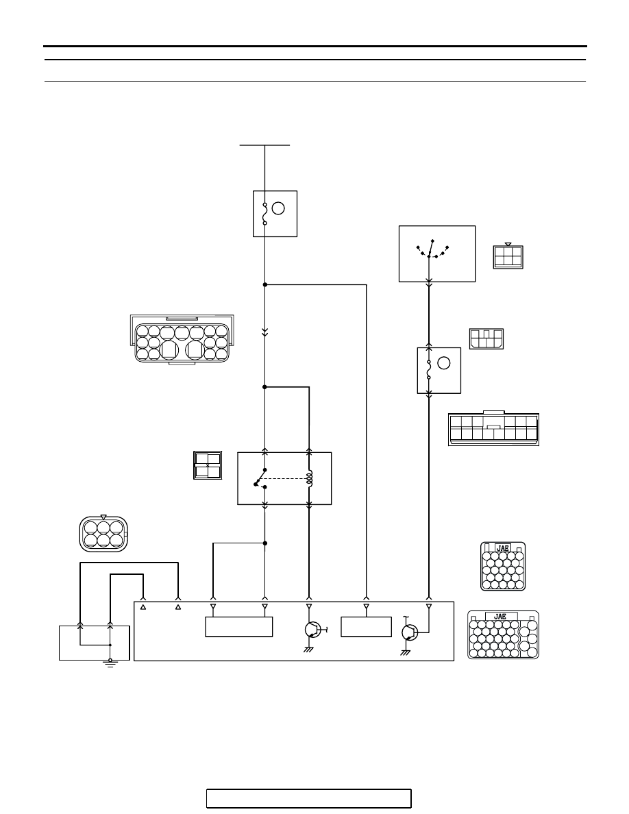
INSPECTION PROCEDURE 28: Power supply system and ignition switch - IG system.

AK400836

6

2 3

4 5 6

BLA

CK-

WHITE

1

1

3

2

4 5

BLA

CK-ORANGE

RED-WHITE

RED

RED

RED

SKY BLUE

RED-

WHITE

RED-

WHITE

RED-

WHITE

RED-

WHITE

WHITE

BLA

CK

BATTERY

R

IG2

ST

LOCK

ACC

IG1

C-308

   C-215
MU801331

IGNITION
SWITCH

2

6

1

JUNCTION  BLOCK

43

42

MFI
RELAY

B-17X

A-14

(MU802755)

1

2

4

3

52

BATTERY
BACKUP

64

51

POWER
SOURCE

BLA

C

K

29

POWERTRAIN CONTROL
MODULE (PCM)

GROUNDING
CONNECTOR

     B-20

     B-21

5

9

20A

25

17

7.5A

RELAY
BOX

Power Supply and Ignition Switch-IG Circuit

3 4

1 2

    C-214
(MU801857)

A-13

1 2 3

4 5 6

7

12

11

10

14

13

9

8

1 2

3 4 5

14

15

8 9

12 13

6 7

10 11
16 17

RED-
WHITE

22

21

23 24 25

26 27 28 29

30 31 32 33 34

35 36 37 38

39 40 41 42 43

52

51

53 54 55 56

57

58 59 60 61 62

63

64 65 66 67 68 69

70

71 72 73 74 75

76

77 78 79 80 81 82

83

3

2

OFF

ON

1

2 3

4

5 6

MULTIPORT FUEL INJECTION (MFI) DIAGNOSIS

TSB Revision

MULTIPORT FUEL INJECTION (MFI) <3.8L ENGINE>

13B-1097

.

AK303241

CONNECTORS: B-20, 21

PCM

AB

AIR CLEANER

B-20

B-21 (B)

AK303148

CONNECTOR: A-13

AB

A-13(GR)

1

2

3

4

1

2

3

4

1

2

3

4

1

2

3

4

AK303014

CONNECTOR: B-17X

MFI RELAY

MFI RELAY

FRONT OF VEHICLE

B-17X

AB

AK203191

CONNECTOR: C-308

C-308

AB

AK303243

CONNECTOR: C-214

AB

JUNCTION
BLOCK

C-214

AK303244

CONNECTOR: C-215

AB

JUNCTION
BLOCK

C-215

AK303190

CONNECTOR: A-14

A-14 (GR)

AB

MULTIPORT FUEL INJECTION (MFI) DIAGNOSIS

TSB Revision

MULTIPORT FUEL INJECTION (MFI) <3.8L ENGINE>

13B-1098

CIRCUIT OPERATION

• Battery positive voltage is applied to the MFI 

relay (terminals No. 1, No. 2).

• When the ignition switch is turned to the "ON" 

position, the battery positive voltage is applied to 
the PCM (terminal No. 43). When the battery pos-
itive voltage is applied, the PCM turns the power 
transistor in the PCM "ON" and grounds the MFI 
relay coil. With this, the MFI relay turns "ON" and 
the battery positive voltage is supplied to the 
PCM (terminals No. 51, No. 64) from the MFI 
relay (terminal No. 4).

• A battery positive voltage is constantly supplied 

to the PCM (terminal No. 42) as the backup 
power.

• The PCM (terminals No. 25, No. 29) is grounded 

to the vehicle body.

.

TROUBLESHOOTING HINTS (The most 
likely causes for this code to be set are:) 

• Malfunction of the ignition switch.

• Malfunction of the MFI relay.

• Improper connector contact, open circuit or 

short-circuit harness wire.

• Disconnected PCM ground wire.

• Malfunction of the PCM.

DIAGNOSIS

STEP 1. Check harness connector B-17X at MFI relay for 
damage.
Q: Is the connector in good condition?

YES : Go to Step 2.
NO :  Repair or replace it. Refer to GROUP 00E, Harness 

Connector Inspection 

P.00E-2

. Then confirm that the 

malfunction symptom is eliminated.

1

2

3

4

AK303017

CONNECTOR: B-17X

FRONT OF VEHICLE

B-17X

AB

HARNESS
CONNECTOR:
COMPONENT SIDE

RELAY BOX

MULTIPORT FUEL INJECTION (MFI) DIAGNOSIS

TSB Revision

MULTIPORT FUEL INJECTION (MFI) <3.8L ENGINE>

13B-1099

STEP 2. Check the MFI relay.

CAUTION

Because it is not possible to distinguish the top and the 
bottom of the MFI relay, inspect it with the triangle mark 
printed on the relay facing upward.
(1) Remove the MFI relay.

(2) Check for continuity between the MFI relay terminals No. 2 

and No. 3.

• There should be continuity. (approximately 70 ohms)

(3) Use jumper wires to connect MFI relay terminal No. 2 to the 

positive battery terminal and terminal No. 3 to the negative 
battery terminal.

(4) Check for continuity between the MFI relay terminals No. 1 

and No. 4 while connecting and disconnecting the jumper 
wire at the negative battery terminal.

• Should be less than 2 ohms. (Negative battery terminal 

connected)

• Should be open loop. (Negative battery terminal discon-

nected)

(5)  Install the MFI relay.
Q: Is the measured resistance within the specified range?

YES : Go to Step 3.
NO :  Replace the MFI relay. Then confirm that the 

malfunction symptom is eliminated.

1

2

3

4

AK303017

CONNECTOR: B-17X

FRONT OF VEHICLE

B-17X

AB

HARNESS
CONNECTOR:
COMPONENT SIDE

RELAY BOX

AK204164

1

2

3

4

MFI RERAY 
SIDE 
CONNECTOR

AB

1

2

3

4

AK203257

MFI RELAY SIDE
CONNECTOR

AB


Content   ..  1197  1198  1199  1200   ..