Mitsubishi Galant 9G. Manual - part 1196


  Index      Mitsubishi     Mitsubishi Galant 9G - service repair manual


Search            


Content   ..  1194  1195  1196  1197   ..


Mitsubishi Galant 9G. Manual - part 1196


MULTIPORT FUEL INJECTION (MFI) DIAGNOSIS

TSB Revision

MULTIPORT FUEL INJECTION (MFI) <3.8L ENGINE>

13B-1084

STEP 13. Check the EGR system.
Refer to GROUP 17, Emission Control System 

− General 

Description (EGR System) 

P.17-89

.

Q: Is the EGR system normal?

YES : Go to Step 14.
NO :  Repair or replace it. Then confirm that the malfunction 

symptom is eliminated.

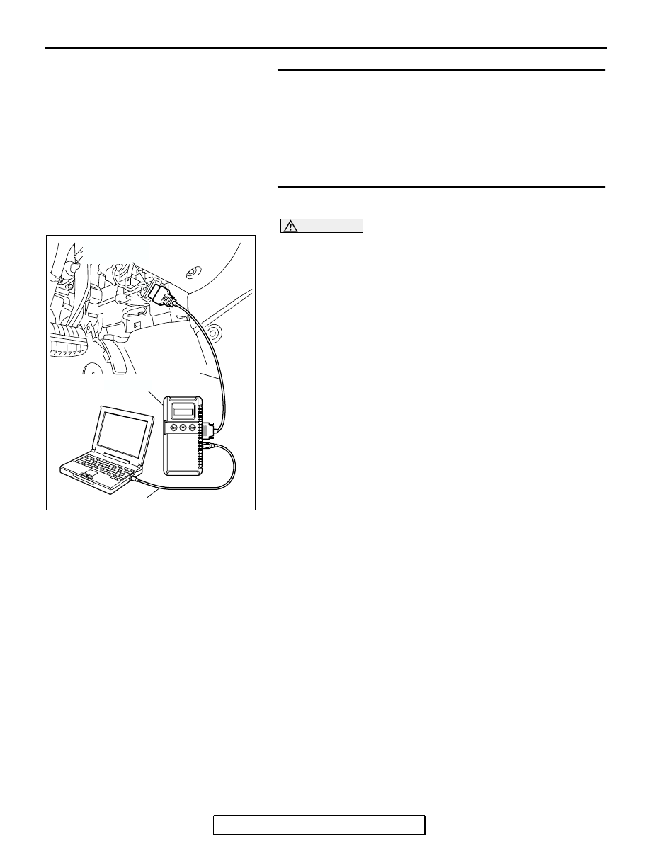
STEP 14. Using scan tool MB991958, check data list item 
59: Heated oxygen sensor bank 2, sensor 2 (left rear).

CAUTION

To prevent damage to scan tool MB991958, always turn the 
ignition switch to the "LOCK" (OFF) position before con-
necting or disconnecting scan tool MB991958.
(1) Connect scan tool MB991958 to the data link connector.
(2) Start the engine and run at idle.
(3) Set scan tool MB991958 to the data reading mode for item 

59, Heated Oxygen Sensor bank 2, sensor 2 (left rear).

• Average voltage should be 0.6 volt or less, when idling.

(4) Turn the ignition switch to the "LOCK" (OFF) position.
Q: Is the sensor operating properly?

YES : Go to Step 16.
NO :  Replace the left bank heated oxygen sensor (front). 

Then confirm that the malfunction symptom is 
eliminated.

STEP 15. Check the fuel pressure.
Refer to On-vehicle Service 

− Fuel Pressure Test 

P.13B-1179

.

Q: Is the fuel pressure normal?

YES : Go to Step 16.
NO :  Repair or replace it. Then confirm that the malfunction 

symptom is eliminated.

AC305412

AB

MB991910

DATA LINK

CONNECTOR

MB991824

MB991827

MULTIPORT FUEL INJECTION (MFI) DIAGNOSIS

TSB Revision

MULTIPORT FUEL INJECTION (MFI) <3.8L ENGINE>

13B-1085

STEP 16. Check the following items.
(1) Check the following items, and repair or replace the 

defective items.

a. Check the injectors for fuel leakage.
b. Check the ignition coil and spark plugs.

c. Check compression pressure.

d. Check the positive crankcase ventilation system.
e. Check the evaporative emission system.

(2) Then check the malfunction symptom.
Q: Is the malfunction symptom eliminated?

YES : The check is completed.
NO :  Replace the catalytic converter. Then confirm that the 

malfunction symptom is eliminated.

INSPECTION PROCEDURE 24: Purge Flow Test of the Evaporative Emission Canister Failure.

.

COMMENT

• The test fails when the purge line or purge port is 

clogged or if the evaporative emission purge 
solenoid fails.

.

TROUBLESHOOTING HINTS (The most 
likely causes for this case:)

• Purge line or purge port is clogged.

• Malfunction of the evaporative emission purge 

solenoid.

• Evaporative emission canister is clogged.

DIAGNOSIS

Required Special Tools:

• MB991958: Scan Tool (MUT-III Sub Assembly)

• MB991824: V.C.I.

• MB991827: USB Cable

• MB991910: Main Harness A

MULTIPORT FUEL INJECTION (MFI) DIAGNOSIS

TSB Revision

MULTIPORT FUEL INJECTION (MFI) <3.8L ENGINE>

13B-1086

STEP 1. Using scan tool MB991958, read the diagnostic 
trouble code (DTC).

CAUTION

To prevent damage to scan tool MB991958, always turn the 
ignition switch to the "LOCK" (OFF) position before con-
necting or disconnecting scan tool MB991958.
(1) Connect scan tool MB991958 to the data link connector.
(2) Turn the ignition switch to the "ON" position.
(3) Read the DTC.
(4) Turn the ignition switch to the "LOCK" (OFF) position.
Q: Is the DTC set?

YES : Refer to Diagnostic Trouble Code Chart 

P.13B-34

.

NO :  Refer to GROUP 17, Emission Control System 

− 

Purge Control System Check (Purge Flow Check) 

P.17-86

.

INSPECTION PROCEDURE 25: Pressure Test of the Evaporative System Failure

.

COMMENT

• The test fails if there is a leak from the fuel tank or 

vapor line.

.

TROUBLESHOOTING HINTS (The most 
likely causes for this case:)

• Loose fuel tank filler tube cap.

• Broken seal in fuel tank, vapor line evaporative 

emission canister.

DIAGNOSIS

STEP 1. Check the evaporative emission purge solenoid.
Refer to GROUP 17, Emission Control System 

− Evaporative 

Emission Purge Solenoid Check 

P.17-87

.

Q: Is the evaporative emission purge solenoid normal?

YES : Go to Step 2.
NO :  Repair or replace it. Then confirm that the malfunction 

symptom is eliminated.

AC305412

AB

MB991910

DATA LINK

CONNECTOR

MB991824

MB991827

MULTIPORT FUEL INJECTION (MFI) DIAGNOSIS

TSB Revision

MULTIPORT FUEL INJECTION (MFI) <3.8L ENGINE>

13B-1087

STEP 2. Check the evaporative emission ventilation 
solenoid.
Refer to GROUP 17, Emission Control System 

− Evaporative 

Emission Ventilation Solenoid Check 

P.17-88

.

Q: Is the evaporative emission ventilation solenoid 

normal?
YES : 
Check the following items, and repair or replace the 

defective items.

a. Check for leaks from the vapor line or 

evaporative emission canister.

b. Check for leaks from the fuel tank.

Then confirm that the malfunction symptom is 

eliminated.

NO :  Repair or replace it. Then confirm that the malfunction 

symptom is eliminated.

INSPECTION PROCEDURE 26: Generator output voltage is low (approximately 12.3 volts).

AK302876

BLA

CK-RED

POWERTRAIN CONTROL
MODULE (PCM)

GENERATOR

VOLTAGE
REGULATOR

      B-116
(MU802046)

1

132

      B-23

Generator Circuit

4

3

2

1

121 122 123 124 125 126 127

128 129 130 131 132 133

134 135 136 137 138 139 140

141 142 143 144 145 146

147 148 149 150 151 152 153


Content   ..  1194  1195  1196  1197   ..