Mitsubishi Galant 9G. Manual - part 1190


  Index      Mitsubishi     Mitsubishi Galant 9G - service repair manual


Search            


Content   ..  1188  1189  1190  1191   ..


Mitsubishi Galant 9G. Manual - part 1190


MULTIPORT FUEL INJECTION (MFI) DIAGNOSIS

TSB Revision

MULTIPORT FUEL INJECTION (MFI) <3.8L ENGINE>

13B-1060

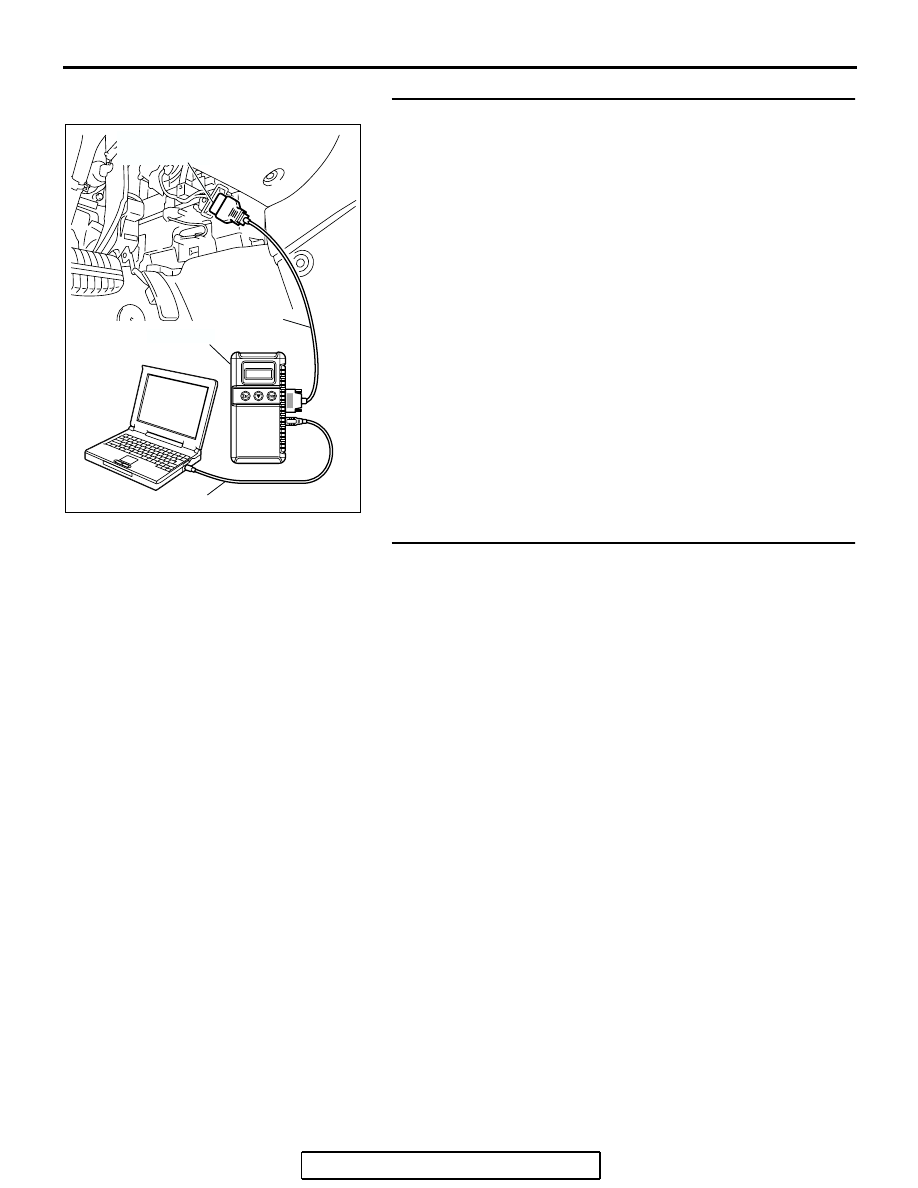
STEP 3. Using scan tool MB991958, check data list.
(1) Turn the ignition switch to the "ON" position.
(2) Check the following items in the data list. Refer to Data List 

Reference Tabl

P.13B-1137

.

a. Item 79: Throttle Position Sensor (main).
b. Item 14: Throttle Position Sensor (sub).

c. Item 78: Accelerator Pedal Position Sensor (main).

d. Item 77: Accelerator Pedal Position Sensor (sub).

(3) Turn the ignition switch to the "LOCK" (OFF) position.
Q: Are they operating properly?

YES : Go to Step 4.
NO :  Repair or replace it. Then confirm that the malfunction 

symptom is eliminated.

STEP 4. Inspection of throttle body (throttle valve area) for 
dirtiness.
Q: Is the throttle valve area dirty?

YES : Refer to On-vehicle Service 

− Clean the throttle valve 

area 

P.13B-1178

.

NO :  Check the following items, and repair, replace or 

clean the defective sections.

a. Check the ignition coil and spark plugs.
b. Check the EGR valve.

Then confirm that the malfunction symptom is 

eliminated.

AC305412

AB

MB991910

DATA LINK

CONNECTOR

MB991824

MB991827

MULTIPORT FUEL INJECTION (MFI) DIAGNOSIS

TSB Revision

MULTIPORT FUEL INJECTION (MFI) <3.8L ENGINE>

13B-1061

INSPECTION PROCEDURE 15: Hesitation, sag or stumble.

.

COMMENT

• In cases such as the above, the ignition system, 

air/fuel mixture compression pressure may be 
defective.

.

TROUBLESHOOTING HINTS (The most 
likely causes for this case:)

• Malfunction of the ignition system.

• Malfunction of air/fuel ratio control system.

• Malfunction of the fuel supply system.

• Malfunction of the EGR system.

• Poor compression pressure.

DIAGNOSIS

Required Special Tools:

• MB991958: Scan Tool (MUT-III Sub Assembly)

• MB991824: V.C.I.

• MB991827: USB Cable

• MB991910: Main Harness A

STEP 1. Using scan tool MB991958, read the diagnostic 
trouble code (DTC).

CAUTION

To prevent damage to scan tool MB991958, always turn the 
ignition switch to the "LOCK" (OFF) position before con-
necting or disconnecting scan tool MB991958.
(1) Connect scan tool MB991958 to the data link connector.
(2) Turn the ignition switch to the "ON" position.
(3) Read the DTC.
(4) Turn the ignition switch to the "LOCK" (OFF) position.
Q: Is the DTC set?

YES : Refer to Diagnostic Trouble Code Chart 

P.13B-34

.

NO :  Go to Step 2.

AC305412

AB

MB991910

DATA LINK

CONNECTOR

MB991824

MB991827

MULTIPORT FUEL INJECTION (MFI) DIAGNOSIS

TSB Revision

MULTIPORT FUEL INJECTION (MFI) <3.8L ENGINE>

13B-1062

STEP 2. Using scan tool MB991958, check actuator test 
items 01, 02, 03, 04, 05, 06: Injector.
(1) Check following items in the actuator test. Refer to Actuator 

Test Reference Table 

P.13B-1152

.

a. Item 01, 02, 03, 04, 05, 06: Injector.

(2) Turn the ignition switch to the "LOCK" (OFF) position.
Q: Are thy operating properly?

YES : Go to Step 3.
NO :  Refer to DTC P0201

P.13B-481

, P0202

P.13B-493

P0203

P.13B-504

, DTC P0204

P.13B-516

P0205

P.13B-527

, P0206

P.13B-539


− Injector Circuit.

STEP 3. Check the ignition timing.
(1) Refer to GROUP 11, On-vehicle Service 

− Ignition Timing 

Check 

P.11C-8

.

Q: Is the ignition timing normal?

YES : Go to Step 4.
NO :  Check that the crankshaft position sensor and timing 

belt cover are in the correct position. Then confirm 
that the malfunction symptom is eliminated.

AC305412

AB

MB991910

DATA LINK

CONNECTOR

MB991824

MB991827

MULTIPORT FUEL INJECTION (MFI) DIAGNOSIS

TSB Revision

MULTIPORT FUEL INJECTION (MFI) <3.8L ENGINE>

13B-1063

STEP 4. Using scan tool MB991958, check data list and 
actuator test.

CAUTION

To prevent damage to scan tool MB991958, always turn the 
ignition switch to the "LOCK" (OFF) position before con-
necting or disconnecting scan tool MB991958.
(1) Connect scan tool MB991958 to the data link connector.
(2) Turn the ignition switch to the "ON" position.
(3) Check the following items in the data list. Refer to Data List 

Reference Tabl

P.13B-1137

.

a. Item 13: Intake Air Temperature Sensor.
b. Item 25: Barometric Pressure Sensor.

c. Item 21: Engine Coolant Temperature Sensor.

d. Item 69: Right Bank Heated Oxygen Sensor (rear).
e. Item 39: Right Bank Heated Oxygen Sensor (front).

f. Item 59: Left Bank Heated Oxygen Sensor (rear).

g. Item 11: Left Bank Heated Oxygen Sensor (front).

(4) Turn the ignition switch to the "LOCK" (OFF) position.
Q: Are they operating properly?

YES : Go to Step 5.
NO :  Repair or replace it. Then confirm that the malfunction 

symptom is eliminated.

STEP 5. Using scan tool MB991958, check data list.
(1) Turn the ignition switch to the "ON" position.
(2) Check the following items of data list. Refer to Data List 

Reference Tabl

P.13B-1137

.

a. Item 39: Right Bank Heated Oxygen Sensor (front).
b. Item 11: Left Bank Heated Oxygen Sensor (front).

• Voltage should fluctuate between 0 − 0.4 volt and 0.6 − 

1.0 volt while idling after the engine has warmed-up.

(3) Turn the ignition switch to the "LOCK" (OFF) position.
Q: Is the sensor operating properly?

YES : Go to Step 7.
NO :  Go to Step 6.

AC305412

AB

MB991910

DATA LINK

CONNECTOR

MB991824

MB991827

AC305412

AB

MB991910

DATA LINK

CONNECTOR

MB991824

MB991827


Content   ..  1188  1189  1190  1191   ..