Mitsubishi Galant 9G. Manual - part 1169


  Index      Mitsubishi     Mitsubishi Galant 9G - service repair manual


Search            


Content   ..  1167  1168  1169  1170   ..


Mitsubishi Galant 9G. Manual - part 1169


MULTIPORT FUEL INJECTION (MFI) DIAGNOSIS

TSB Revision

MULTIPORT FUEL INJECTION (MFI) <3.8L ENGINE>

13B-976

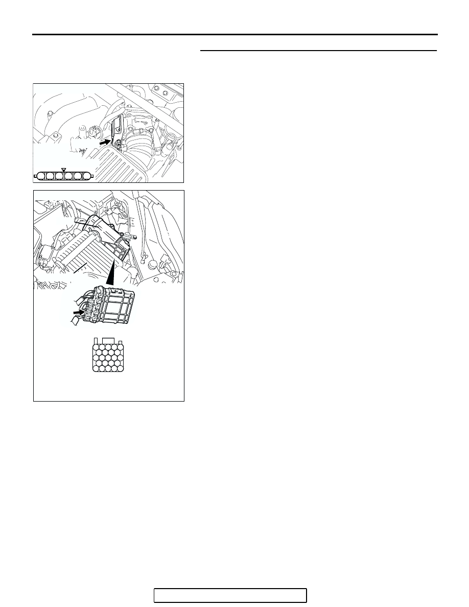
STEP 2. Check for short circuit to ground between throttle 
position sensor connector B-06 (terminal No. 4) and PCM 
connector B-22 (terminal No. 99).
Q: Is the harness wire in good condition?

YES : Go to Step 3.
NO :  Repair it. Then go to Step 5.

2 1

6 5 4 3

AK303044

HARNESS
CONNECTOR:
COMPONENT SIDE

B-06 (B)

CONNECTOR: B-06

AB

AK303016

104

96

94

95

93 92 91

99 98 97

103 102 101 100

108 107 106 105

113 112 111 110 109

CONNECTOR: B-22

B-22 (B)

PCM

AB

HARNESS CONNECTOR: 
COMPONENT SIDE

AIR CLEANER

MULTIPORT FUEL INJECTION (MFI) DIAGNOSIS

TSB Revision

MULTIPORT FUEL INJECTION (MFI) <3.8L ENGINE>

13B-977

STEP 3. Check for short circuit to ground between throttle 
position sensor connector B-06 (terminal No. 6) and PCM 
connector B-22 (terminal No. 98).
Q: Is the harness wire in good condition?

YES : Go to Step 4.
NO :  Repair it. Then go to Step 5.

STEP 4. Replace the throttle body assembly.
(1) Replace the throttle body assembly.
(2) Turn the ignition switch to the "ON" position.
(3) After the DTC has been deleted, read the DTC again.
(4) Turn the ignition switch to the "LOCK" (OFF) position.
Q: Is DTC P2135 set?

YES : Replace the PCM. Then go to Step 5.
NO :  The inspection is complete.

2 1

6 5 4 3

AK303044

HARNESS
CONNECTOR:
COMPONENT SIDE

B-06 (B)

CONNECTOR: B-06

AB

AK303016

104

96

94

95

93 92 91

99 98 97

103 102 101 100

108 107 106 105

113 112 111 110 109

CONNECTOR: B-22

B-22 (B)

PCM

AB

HARNESS CONNECTOR: 
COMPONENT SIDE

AIR CLEANER

2 1

6 5 4 3

AK303044

HARNESS
CONNECTOR:
COMPONENT SIDE

B-06 (B)

CONNECTOR: B-06

AB

MULTIPORT FUEL INJECTION (MFI) DIAGNOSIS

TSB Revision

MULTIPORT FUEL INJECTION (MFI) <3.8L ENGINE>

13B-978

STEP 5. Using scan tool MB991958, read the diagnostic 
trouble code (DTC).

CAUTION

To prevent damage to scan tool MB991958, always turn the 
ignition switch to the "LOCK"(OFF) position before con-
necting or disconnecting scan tool MB991958.
(1) Connect scan tool MB991958 to the data link connector.
(2) Turn the ignition switch to the "ON" position.
(3) After the DTC has been deleted, read the DTC again.
(4) Turn the ignition switch to the "LOCK"(OFF) position.
Q: Is DTC P2135 set?

YES : Retry the troubleshooting.
NO :  The inspection is complete.

DTC P2138: Accelerator Pedal Position Sensor (main and sub) Circuit Range/Performance Problem

CAUTION

If DTC P2138 has been set, TCL related DTC 
U1120 and U1400 are also set. After P2138 has 
been diagnosed, don't forget to erase DTC U1120 
and U1400.

.

ACCELERATOR PEDAL POSITION 
SENSOR (MAIN AND SUB) 
RANGE/PERFORMANCE CIRCUIT

• Refer to DTC P2122 − Accelerator Pedal Position 

Sensor (Main) Circuit 

P.13B-938

.

• Refer to DTC P2127 − Accelerator Pedal Position 

Sensor (Sub) Circuit 

P.13B-955

.

.

CIRCUIT OPERATION

• Refer to DTC P2122 − Accelerator Pedal Position 

Sensor (Main) Circuit 

P.13B-938

.

• Refer to DTC P2127 − Accelerator Pedal Position 

Sensor (Sub) Circuit 

P.13B-955

.

.

TECHNICAL DESCRIPTION

• PCM checks the accelerator pedal position sen-

sor output signal characteristics for abnormal 
conditions.

.

DESCRIPTIONS OF MONITOR METHODS

Detect malfunction if the relation between accelera-

tor pedal position sensor (main) and accelerator 
pedal position sensor (sub) is wrong.

.

MONITOR EXECUTION

Continuous

.

MONITOR EXECUTION CONDITIONS 
(Other monitor and Sensor)

Other Monitor (There is no temporary DTC stored 

in memory for the item monitored below)

• Not applicable

Sensor (The sensor below is determined to be 

normal)

• Not applicable

.

AC305412

AB

MB991910

DATA LINK

CONNECTOR

MB991824

MB991827

MULTIPORT FUEL INJECTION (MFI) DIAGNOSIS

TSB Revision

MULTIPORT FUEL INJECTION (MFI) <3.8L ENGINE>

13B-979

DTC SET CONDITIONS 
<Range/Performance problem -relation between main and sub>
Logic Flow Chart

.

Check Condition

• Ignition switch is "ON" position.

• Accelerator pedal position sensor (main) output 

voltage is between 0.6 and 4.8 volts.

• Accelerator pedal position sensor (sub) output 

voltage is between 0.2 and 4.8 volts.

• Change of accelerator pedal position sensor 

(sub) output voltage per 25 milliseconds is lower 
than 0.06 volt.

Judgement Criteria

• Voltage obtained with the formula given below is 

1.0 volt or higher for 1 second: [accelerator pedal 
position sensor (sub) output voltage +0.3 volt] 

− 

accelerator pedal position sensor (main) output 
voltage.

.

AK303910

START

END

NO

NO

YES

YES

YES

NO

MALFUNCTION

GOOD

CONTINUOUS

FAILURE FOR 1sec

{APS (SUB) +0.3V} -

APS (MAIN)

> =1.0V

MONITORING

CONDITIONS


Content   ..  1167  1168  1169  1170   ..