Mitsubishi Galant 9G. Manual - part 1155


  Index      Mitsubishi     Mitsubishi Galant 9G - service repair manual


Search            


Content   ..  1153  1154  1155  1156   ..


Mitsubishi Galant 9G. Manual - part 1155


MULTIPORT FUEL INJECTION (MFI) DIAGNOSIS

TSB Revision

MULTIPORT FUEL INJECTION (MFI) <3.8L ENGINE>

13B-920

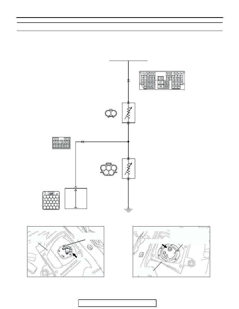
DTC P2066: Fuel Level Sensor (sub) Circuit Range/Performance 

1

2 3

4

5

22

21

23 24 25

26 27 28 29

30 31 32 33 34

35 36 37 38

39 40 41 42 43

1

2

AK400894

Fuel Level Sensor Circuit

FUEL LEVEL
SENSOR (SUB)

FUEL LEVEL SENSOR (MAIN)
(INTEGRATED IN FUEL PUMP MODULE)

13

2

1

2

1

11

PINK-

BLA

CK

BLA

CK

PINK-
BLACK

PINK-

BLA

CK

PINK-BLA

CK

24

GRA

Y

GRA

Y

POWERTRAIN 
CONTROL
MODULE (PCM) 

C-28

C-25

D-18

(MU802058)

D-17

CONBINATION METER

B-20

AK303156

CONNECTOR: D-17

AB

SERVICE
HOLE

FUEL LEVEL
SENSOR (SUB)

D-17

AK303157

SERVICE
HOLE

AB

FUEL PUMP MODULE
(INCORPORATING FUEL
LEVEL SENSOR (MAIN)
AND FUEL TANK
TEMPERATURE SENSOR)

CONNECTOR: D-18

D-18 (GR)

MULTIPORT FUEL INJECTION (MFI) DIAGNOSIS

TSB Revision

MULTIPORT FUEL INJECTION (MFI) <3.8L ENGINE>

13B-921

.

CIRCUIT OPERATION

• The fuel level sensor (sub) drive signal is input in 

combination meter (terminal No. 13).

.

TECHNICAL DESCRIPTION

• Branch the drive signal from the fuel level sensor 

circuit, and input it into combination meter.

• The combination meter detects the amount of 

fuel left in the fuel tank with this signal, and also 
controls the fuel level warning light.

.

DESCRIPTIONS OF MONITOR METHODS

Detect malfunction if change of fuel level sensor out-

put voltage is small when sum of fuel injection is 
large.

.

MONITOR EXECUTION

Continuous

.

MONITOR EXECUTION CONDITIONS 
(Other monitor and Sensor)

Other Monitor (There is no temporary DTC stored 

in memory for the item monitored below)

• Not applicable

Sensor (The sensor below is determined to be 

normal)

• Not applicable

.

AK303085

CONNECTOR: B-20

PCM

AB

AIR CLEANER

B-20

AK303188

CONNECTOR: C-28

C-28

AB

AK303086

CONNECTOR: C-25

C-25

AB

MULTIPORT FUEL INJECTION (MFI) DIAGNOSIS

TSB Revision

MULTIPORT FUEL INJECTION (MFI) <3.8L ENGINE>

13B-922

DTC SET CONDITIONS
Logic Flow Chart

.

INDICATED FUEL LEVEL

CHANGE < 2L

ACCUMULATE FUEL CONSUMPTION

THROUGH FUEL INJECTORS.

ACCUMULATED FUEL 
CONSUMPTION WILL NOT 
RESET WHEN KEY-OFF/ON.

ACCUMULATED FUEL 

CONSUMPTION > =30L

START

END

NO

NO

NO

YES

YES

YES

MALFUNCTION

GOOD

MONITORING

CONDITIONS

RESET ACCUMULATE

FUEL CONSUMPTION.

AK302407

MULTIPORT FUEL INJECTION (MFI) DIAGNOSIS

TSB Revision

MULTIPORT FUEL INJECTION (MFI) <3.8L ENGINE>

13B-923

Check Conditions, Judgement Criteria

• When the fuel consumption calculated from the 

operation time of the injector amounts to 30 lit-
ters, the diversity of the amount of fuel in tank cal-
culated from the fuel level sensor is 2 litters or 
less.

.

OBD-II DRIVE CYCLE PATTERN

Refer to Diagnostic Function 

− OBD-II Drive Cycle − 

Procedure 6 

− Other Monitor 

P.13B-6

.

.

TROUBLESHOOTING HINTS (The most 
likely causes for this code to be set are:)

• Fuel pump module or fuel level sensor (sub) 

failed.

• PCM failed.

DIAGNOSIS

Required Special Tools:

• MB991958: Scan tool (MUT-III Sub Assembly)

• MB991824: V.C.I.

• MB991827: USB Cable

• MB991910: Main Harness A

STEP 1. Using scan tool MB991958, read the diagnostic 
trouble code (DTC).

CAUTION

To prevent damage to scan tool MB991958, always turn the 
ignition switch to the "LOCK" (OFF) position before con-
necting or disconnecting scan tool MB991958.
(1) Connect scan tool MB991958 to the data link connector.
(2) Turn the ignition switch to the "ON" position.
(3) Read the DTC.
(4) Turn the ignition switch to the "LOCK" (OFF) position.
Q: Is DTC P0461 set?

YES : Go to Step 2.
NO :  Go to Step 4.

STEP 2. Check fuel gauge.
Q: Is the fuel gauge functioning?

YES : Go to Step 3.
NO :  Refer to GROUP 54A, Chasiss Electrical 

− 

Combination Meters Assembly and Vehicle Speed 
Sensor 

− Symptom Chart 

P.54A-16

.

AC305412

AB

MB991910

DATA LINK

CONNECTOR

MB991824

MB991827


Content   ..  1153  1154  1155  1156   ..