Mitsubishi Galant 9G. Manual - part 1147


  Index      Mitsubishi     Mitsubishi Galant 9G - service repair manual


Search            


Content   ..  1145  1146  1147  1148   ..


Mitsubishi Galant 9G. Manual - part 1147


MULTIPORT FUEL INJECTION (MFI) DIAGNOSIS

TSB Revision

MULTIPORT FUEL INJECTION (MFI) <3.8L ENGINE>

13B-888

DIAGNOSIS

Required Special Tools:

• MB991958: Scan tool (MUT-III Sub Assembly)

• MB991824: V.C.I.

• MB991827: USB Cable

• MB991910: Main Harness A

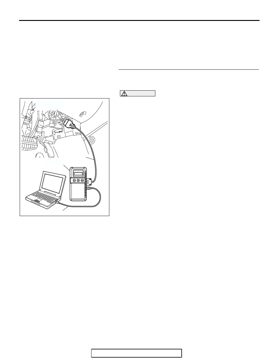
STEP 1. Using scan tool MB991958, check data list item 
9A: Throttle Position Sensor (main) Mid Opening Learning 
Value.

CAUTION

To prevent damage to scan tool MB991958, always turn the 
ignition switch to the "LOCK"(OFF) position before con-
necting or disconnecting scan tool MB991958.
(1) Connect scan tool MB991958 to the data link connector.
(2) Turn the ignition switch to the "ON" position.
(3) Set scan tool MB991958 to the data reading mode for item 

9A, Throttle position sensor (main) mid opening learning 
value.

• Check that it is between 0.6 and 1.2 volts.

(4) Turn the ignition switch to the "LOCK"(OFF) position.
Q: Is the measured voltage 4 volts or less?

YES : Go to Step 2..
NO :  Replace the throttle body assembly. Then go to Step 

8.

AC305412

AB

MB991910

DATA LINK

CONNECTOR

MB991824

MB991827

MULTIPORT FUEL INJECTION (MFI) DIAGNOSIS

TSB Revision

MULTIPORT FUEL INJECTION (MFI) <3.8L ENGINE>

13B-889

STEP 2. Check the throttle actuator control motor.
(1) Disconnect the connector B-06.

(2) Measure the resistance between throttle actuator control 

motor side connector terminal No. 1 and No. 2.

Standard value: 0.3 

 80 ohms [at 20°C (68°F)]

Q: Is the measured resistance between 0.3 and 80 ohms [at 

20

°C (68°F)]?

YES : Go to Step 3.
NO :  Replace the throttle body assembly. Then go to Step 

8.

STEP 3. Check harness connector B-06 at throttle actuator 
control motor for damage.
Q: Is the harness connector in good condition?

YES : Go to Step 4.
NO :  Repair or replace it. Refer to GROUP 00E, Harness 

Connector Inspection 

P.00E-2

. Then go to Step 8..

2 1

6 5 4 3

AK303044

HARNESS
CONNECTOR:
COMPONENT SIDE

B-06 (B)

CONNECTOR: B-06

AB

6

1 2 3 4 5

AK202992

THROTTLE ACTUATOR
CONTROL MOTOR 
CONNECTOR

AB

2 1

6 5 4 3

AK303044

HARNESS
CONNECTOR:
COMPONENT SIDE

B-06 (B)

CONNECTOR: B-06

AB

MULTIPORT FUEL INJECTION (MFI) DIAGNOSIS

TSB Revision

MULTIPORT FUEL INJECTION (MFI) <3.8L ENGINE>

13B-890

STEP 4. Check harness connector B-23 at PCM for 
damage.
Q: Is the harness connector in good condition?

YES : Go to Step 5.
NO :  Repair or replace it. Refer to GROUP 00E, Harness 

Connector Inspection 

P.00E-2

. Then go to Step 8.

127 126 125 124 123 122 121

133 132 131 130 129 128

140 139 138 137 136 135 134

146 145 144 143 142 141

153 152 151 150 149 148 147

AK303058

HARNESS CONNECTOR: 
COMPONENT SIDE

CONNECTOR: B-23

B-23

PCM

AB

AIR CLEANER

MULTIPORT FUEL INJECTION (MFI) DIAGNOSIS

TSB Revision

MULTIPORT FUEL INJECTION (MFI) <3.8L ENGINE>

13B-891

STEP 5. Check for harness damage between throttle 
actuator control motor connector B-06 (terminal No. 1) and 
PCM connector B-23 (terminal No. 147).
Q: Is the harness wire in good condition?

YES : Go to Step 6.
NO :  Repair it. Then go to Step 8.

2 1

6 5 4 3

AK303044

HARNESS
CONNECTOR:
COMPONENT SIDE

B-06 (B)

CONNECTOR: B-06

AB

127 126 125 124 123 122 121

133 132 131 130 129 128

140 139 138 137 136 135 134

146 145 144 143 142 141

153 152 151 150 149 148 147

AK303058

HARNESS CONNECTOR: 
COMPONENT SIDE

CONNECTOR: B-23

B-23

PCM

AB

AIR CLEANER


Content   ..  1145  1146  1147  1148   ..