Mitsubishi Galant 9G. Manual - part 1138


  Index      Mitsubishi     Mitsubishi Galant 9G - service repair manual


Search            


Content   ..  1136  1137  1138  1139   ..


Mitsubishi Galant 9G. Manual - part 1138


MULTIPORT FUEL INJECTION (MFI) DIAGNOSIS

TSB Revision

MULTIPORT FUEL INJECTION (MFI) <3.8L ENGINE>

13B-852

DIAGNOSIS

Required Special Tools

• MB991958: Scan tool (MUT-III Sub Assembly)

• MB991824: V.C.I.

• MB991827: USB Cable

• MB991910: Main Harness A

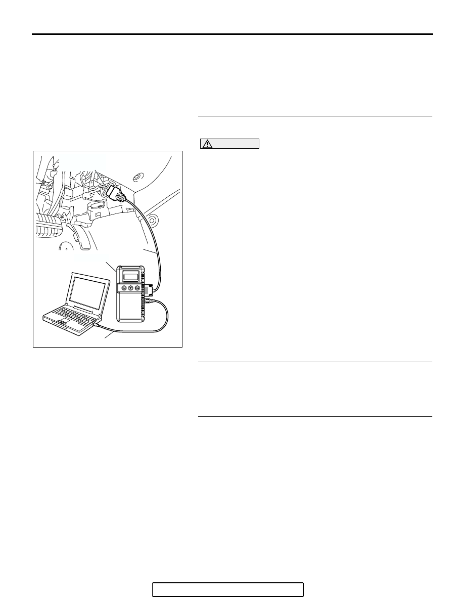
STEP 1. Using scan tool MB991958, read the diagnostic 
trouble code (DTC).

CAUTION

To prevent damage to scan tool MB991958, always turn the 
ignition switch to the "LOCK" (OFF) position before con-
necting or disconnecting scan tool MB991958.
(1) Connect scan tool MB991958 to the data link connector.
(2) Turn the ignition switch to the "ON" position.
(3) After the DTC has been deleted, read the DTC again.
(4) Turn the ignition switch to the "LOCK" (OFF) position.
Q: Is the diagnostic trouble code other than P0507 set?

YES : Refer to Diagnostic Trouble Code Chart 

P.13B-34

.

NO :  Go to Step 2.

STEP 2. Check the intake system vacuum leak.
Q: Are there any abnormalities?

YES : Repair or replace it. Then go to Step 4.
NO :  Go to Step 3.

STEP 3. Replace the throttle body assembly.
(1) Replace the throttle body assembly.
(2) Turn the ignition switch to the "ON" position.
(3) After the DTC has been deleted, read the DTC again.
(4) Turn the ignition switch to the "LOCK" (OFF) position.
Q: Is DTC P0507 set?

YES : Replace the PCM. Then go to Step 4.
NO :  The inspection is complete.

AC305412

AB

MB991910

DATA LINK

CONNECTOR

MB991824

MB991827

MULTIPORT FUEL INJECTION (MFI) DIAGNOSIS

TSB Revision

MULTIPORT FUEL INJECTION (MFI) <3.8L ENGINE>

13B-853

STEP 4. Test the OBD-II drive cycle.
(1) Carry out a test drive with the drive cycle pattern. Refer to 

Procedure 6 

− Other Monitor 

P.13B-6

.

(2) Check the diagnostic trouble code (DTC).
Q: Is DTC P0507 set?

YES : Retry the troubleshooting.
NO :  The inspection is complete.

DTC P0513: Immobilizer Malfunction

.

TECHNICAL DESCRIPTION

• PCM monitors the communication condition with 

the immobilizer-ECU. When an abnormality in 
communication is found, PCM prevents engine 
start.

.

DTC SET CONDITIONS

Check Conditions

• Ignition switch: ON

Judgment Criteria

• When the communication error between PCM 

and the immobilizer-ECU continues for 2 seconds 
or more.

.

TROUBLESHOOTING HINTS (The most likely 

causes for this code to be set are: )

• Malfunction of harness or connector.

• Malfunction of immobilizer-ECU.

• Malfunction of PCM.

DIAGNOSIS

Required Special Tools:

• MB991958: Scan tool (MUT-III Sub Assembly)

• MB991824: V.C.I.

• MB991827: USB Cable

• MB991910: Main Harness A

MULTIPORT FUEL INJECTION (MFI) DIAGNOSIS

TSB Revision

MULTIPORT FUEL INJECTION (MFI) <3.8L ENGINE>

13B-854

STEP 1. Using scan tool MB991958, read the immobilizer 
diagnostic trouble code (DTC).

CAUTION

To prevent damage to scan tool MB991958, always turn the 
ignition switch to the "LOCK" (OFF) position before con-
necting or disconnecting scan tool MB991958.
(1) Connect scan tool MB991958 to the data link connector.
(2) Turn the ignition switch to the "ON" position.
(3) Read the immobilizer-DTC.
(4) Turn the ignition switch to the "LOCK" (OFF) position.
Q: Is the immobilizer-DTC set?

YES : Refer to GROUP 54A, Ignition Switch and 

Immobilizer System 

− Diagnostic Trouble Code Chart 

P.54A-12

.

NO :  If DTC P0513 is output again after the MFI-DTC has 

been erased, replace the PCM. Then check that the 
DTC P0513 does not reset.

DTC P0551: Power Steering Pressure Switch Circuit Range/Performance

AC305412

AB

MB991910

DATA LINK

CONNECTOR

MB991824

MB991827

AK302866

YELLO

W

POWERTRAIN
CONTROL
MODULE (PCM)

1

B-31

(MU801211)

POWER STEERING
PRESSURE SWITCH

78

1

Power Steering Pressure Switch Circuit

B-21

52

51

53 54 55 56

57

58 59 60 61 62

63

64 65 66 67 68 69

70

71 72 73 74 75

76

77 78 79 80 81 82

83

MULTIPORT FUEL INJECTION (MFI) DIAGNOSIS

TSB Revision

MULTIPORT FUEL INJECTION (MFI) <3.8L ENGINE>

13B-855

.

CIRCUIT OPERATION

• A battery positive voltage is applied to the power 

steering pressure switch output terminal (terminal 
No. 1) from the PCM (terminal No. 78) via the 
resistor in the PCM.

.

TECHNICAL DESCRIPTION

• The power steering pressure switch converts the 

existence of a power steering load into a high/low 
voltage, and inputs it into the PCM.

• When the steering wheel is turned, hydraulic 

pressure rises. The power steering pressure 
switch closes, and the applied battery positive 
voltage will be grounded. With this, the power 
steering pressure switch output voltage will fluc-
tuate between 0 and 12 volts.

• While driving with the steering wheel held 

straight, the power steering pressure switch turns 
"OFF".

• The PCM checks whether the power steering 

pressure switch turns "OFF" or "ON" during driv-
ing.

.

DESCRIPTIONS OF MONITOR METHODS

Power steering pressure switch stays on during 

specified go/stop operations.

.

MONITOR EXECUTION

Continuous

.

MONITOR EXECUTION CONDITIONS 
(Other monitor and Sensor)

Other Monitor (There is no temporary DTC stored 

in memory for the item monitored below)

• Not applicable

Sensor (The sensor below is determined to be 

normal)

• Engine coolant temperature sensor

.

AK303161

AB

POWER STEERING
PRESSURE SWITCH

B-31 (B)

CONNECTOR: B-31

AK303119

CONNECTOR: B-21

PCM

AC

AIR CLEANER

B-21(B)


Content   ..  1136  1137  1138  1139   ..