Mitsubishi Galant 9G. Manual - part 1134


  Index      Mitsubishi     Mitsubishi Galant 9G - service repair manual


Search            


Content   ..  1132  1133  1134  1135   ..


Mitsubishi Galant 9G. Manual - part 1134


MULTIPORT FUEL INJECTION (MFI) DIAGNOSIS

TSB Revision

MULTIPORT FUEL INJECTION (MFI) <3.8L ENGINE>

13B-836

DIAGNOSIS

Required Special Tools:

• MB991958: Scan Tool (MUT-III Sub Assembly)

• MB991824: V.C.I.

• MB991827: USB Cable

• MB991910: Main Harness A

STEP 1. Check fuel gauge.
Q: Is the fuel gauge functioning?

YES : Go to Step 2.
NO :  Refer to GROUP 54A, Chassis Electrical 

− 

Combination Meters Assembly and Vehicle Speed 
Sensor 

− Equipment Diagnosis − Symptom Chart 

P.54A-16

.

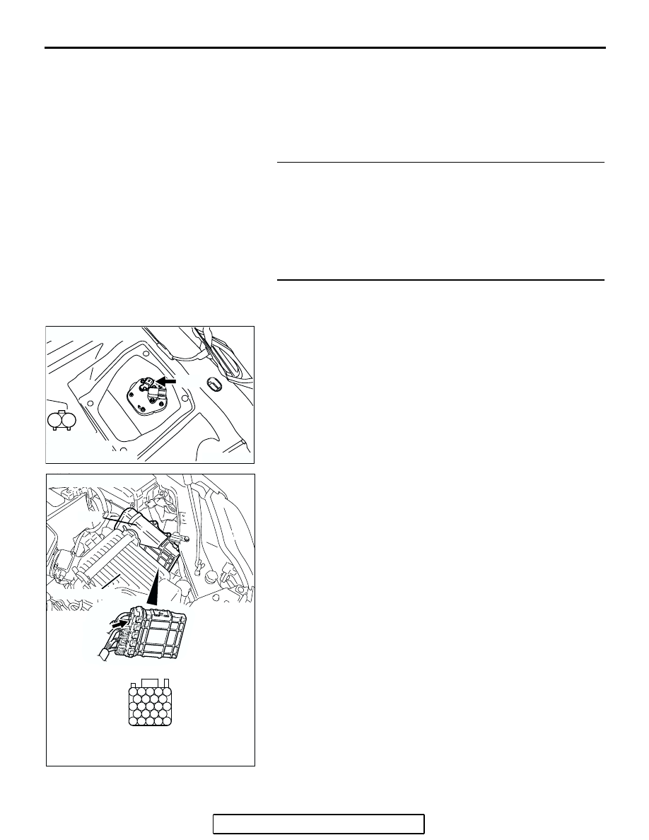
STEP 2. Check harness connector B-20 at PCM and 
harness connector D-17 at fuel level sensor (sub) for 
damage. 
Q: Is the harness connector in good condition?

YES : Go to Step 3.
NO :  Repair or replace them. Refer to GROUP 00E, 

Harness Connector Inspection 

P.00E-2

 Then go to 

Step 7.

AK303878

1

2

AB

CONNECTOR: D-17

D-17

HARNESS 
CONNECTOR:
COMPONENT SIDE

AK303092

25

21

24 23 22

29 28 27 26

34 33 32 31 30

38 37 36 35

43 42 41 40 39

CONNECTOR: B-20

B-20

PCM

AB

HARNESS CONNECTOR: 
COMPONENT SIDE

AIR CLEANER

MULTIPORT FUEL INJECTION (MFI) DIAGNOSIS

TSB Revision

MULTIPORT FUEL INJECTION (MFI) <3.8L ENGINE>

13B-837

STEP 3. Check for short circuit to ground between PCM 
connector B-20 (terminal No. 24) and fuel level sensor 
(sub) connector D-17 (terminal No. 1).

NOTE: Check harness after checking intermediate connectors 
C-25. If intermediate connectors are damaged, repair or 
replace them. Refer to GROUP 00E, Harness Connector 
Inspection 

P.00E-2

. Then go to Step 7.

Q: Is the harness wire in good condition?

YES : Go to Step 4.
NO :  Repair it. Then go to Step 7.

AK303878

1

2

AB

CONNECTOR: D-17

D-17

HARNESS 
CONNECTOR:
COMPONENT SIDE

AK303092

25

21

24 23 22

29 28 27 26

34 33 32 31 30

38 37 36 35

43 42 41 40 39

CONNECTOR: B-20

B-20

PCM

AB

HARNESS CONNECTOR: 
COMPONENT SIDE

AIR CLEANER

MULTIPORT FUEL INJECTION (MFI) DIAGNOSIS

TSB Revision

MULTIPORT FUEL INJECTION (MFI) <3.8L ENGINE>

13B-838

STEP 4. Check harness connector D-18 at fuel level sensor 
(main) for damage. 
Q: Is the harness connector in good condition?

YES : Go to Step 5.
NO :  Repair or replace it. Refer to GROUP 00E, Harness 

Connector Inspection 

P.00E-2

 Then go to Step 7.

STEP 5. Check for short circuit to ground between fuel 
level sensor (main) connector D-18 (terminal No. 2) and 
fuel level sensor (sub) connector D-17 (terminal No. 1).
Q: Is the harness wire in good condition?

YES : Go to Step 6.
NO :  Repair it. Then go to Step 7.

AK303840

1

2

3

4

5

SERVICE
HOLE

AB

CONNECTOR: D-18

D-18 (GR)

HARNESS 
CONNECTOR: 
COMPONENT SIDE

AK303878

1

2

AB

CONNECTOR: D-17

D-17

HARNESS 
CONNECTOR:
COMPONENT SIDE

AK303840

1

2

3

4

5

SERVICE
HOLE

AB

CONNECTOR: D-18

D-18 (GR)

HARNESS 
CONNECTOR: 
COMPONENT SIDE

MULTIPORT FUEL INJECTION (MFI) DIAGNOSIS

TSB Revision

MULTIPORT FUEL INJECTION (MFI) <3.8L ENGINE>

13B-839

STEP 6. Check the trouble symptoms.
(1) Carry out a test drive with the drive cycle pattern. Refer to 

Diagnostic Function 

− OBD-II Drive Cycle − Procedure 6 − 

Other Monitor 

P.13B-6

.

(2) Check the diagnostic trouble code (DTC).
Q: Is DTC P0461 set?

YES : Replace the PCM. Then go to Step 7.
NO :  It can be assumed that this malfunction is intermittent. 

Refer to GROUP 00, How to Use 
Troubleshooting/Inspection Service Points 

− How to 

Cope with Intermittent Malfunctions 

P.00-14

.

STEP 7. Test the OBD-II drive cycle.
(1) Carry out a test drive with the drive cycle pattern. Refer to 

Diagnostic Function 

− OBD-II Drive Cycle − Procedure 6 − 

Other Monitor 

P.13B-6

.

(2) Check the diagnostic trouble code (DTC).
Q: Is DTC P0462 set?

YES : Retry the troubleshooting.
NO :  The inspection is complete.


Content   ..  1132  1133  1134  1135   ..