Mitsubishi Galant 9G. Manual - part 1127


  Index      Mitsubishi     Mitsubishi Galant 9G - service repair manual


Search            


Content   ..  1125  1126  1127  1128   ..


Mitsubishi Galant 9G. Manual - part 1127


MULTIPORT FUEL INJECTION (MFI) DIAGNOSIS

TSB Revision

MULTIPORT FUEL INJECTION (MFI) <3.8L ENGINE>

13B-808

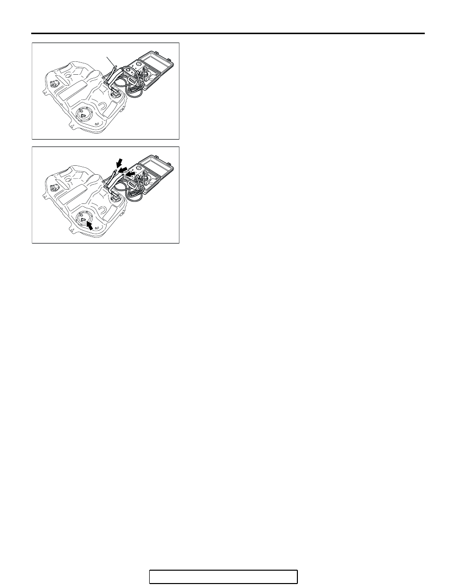
(2) Connect the evaporative emission system pressure pump  

(Miller number 6872A) to the fuel filler hose.

(3) Plug the hose and the nipple shown in the illustration.

NOTE: If these items are not securely plugged now, the fuel 
could leak in the next step.

(4) Pressurize the fuel tank with the evaporative emission 

system pressure pump.

(5) In the pressurized state, check for leaks by applying a 

soapy water solution to each section and look for bubbles.

Q: Are any leaks found?

YES <When there is a leak from the attachment points of 
the fuel pump module, fuel tank differential pressure 
sensor, fuel level sensor (sub) or leveling valve.> : 

Reassemble the leaked parts and check again that 
there are no leaks. Then reinstall the fuel tank (Refer 
to GROUP 13C, Fuel Tank 

P.13C-10

). Then go to 

Step 19   .

YES <When there is a leak from the fuel tank.> : Replace 

the fuel tank (Refer to GROUP 13C, Fuel Tank 

P.13C-10

). Go to Step 19.

NO :  When there is no leak, reinstall the fuel tank (Refer to 

GROUP 13C, Fuel Tank 

P.13C-10

). Then go to Step 

18.

AC305684

FUEL FILLER HOSE

AB

AC305684AC

MULTIPORT FUEL INJECTION (MFI) DIAGNOSIS

TSB Revision

MULTIPORT FUEL INJECTION (MFI) <3.8L ENGINE>

13B-809

STEP 13. Check for clogging in evaporative emission 
system hoses H through J.
(1) Remove the fuel tank filler tube protector (Refer to GROUP 

13C, Fuel Tank 

P.13C-10

).

(2) Use a hand vacuum pump on each hose from hoses H to J.
Q: Are the hoses in good condition?

YES : Go to Step 14.
NO :  Replace the damaged hose, and the fuel tank filler 

tube protector (Refer to GROUP 13C, Fuel Tank 

P.13C-10

). Then go to Step 19.

STEP 14. Test check valve.
(1) Check valve is a one-way check valve.

(2) Check valve should allow air to flow in only one direction.
Q: Does check valve allow air to pass in one direction  

only?
YES : 
Go to Step 15.
NO :  Replace check valve, and reinstall the fuel tank filler 

tube protector (Refer to GROUP 13C, Fuel Tank 

P.13C-10

). Then go to Step 19.

AC306401

HOSE H

AE

AC306800

AC

HOSE I

HOSE J

AC306800

AD

CHECK VALVE

AC306332

AB

CHECK VALVE

MULTIPORT FUEL INJECTION (MFI) DIAGNOSIS

TSB Revision

MULTIPORT FUEL INJECTION (MFI) <3.8L ENGINE>

13B-810

STEP 15. Check for clogging in evaporative emission 
hoses K and L.

Use a hand vacuum pump to test each hose K and L.

Q: Are the hoses in good condition?

YES :  Go to Step 16.
NO :  Replace any damaged hose. Then go to Step 19.

STEP 16. Check the evaporative emission canister for 
leaks and clogging.
(1) Remove the evaporative emission canister (Refer to 

GROUP 17, Evaporative Emission Canister and Fuel Tank 
Pressure Relief Valv

P.17-95

).

(2) Connect a hand vacuum pump to the evaporative emission 

canister and plug the other nipples.

(3) Apply a pressure on the hand vacuum pump, and confirm 

that air is maintained.

(4) When the plugs are removed, check for air leakage.
(5) Disconnect the hand vacuum pump and install the 

evaporative emission canister (Refer to GROUP 17, 
Evaporative Emission Canister and Fuel Tank Pressure 
Relief Valve 

P.17-95

).

Q: Is the evaporative emission canister in good condition?

YES : Go to Step 17.
NO :  Replace the evaporative emission canister (Refer to 

GROUP 17, Evaporative Emission Canister and Fuel 
Tank Pressure Relief Valve 

P.17-95

). Then go to Step 

19   .

STEP 17. Check for clogging in evaporative emission hose 
M.
(1) Remove the fuel tank assembly (Refer to GROUP 13C, 

Fuel Tank 

P.13C-10

).

(2) Use the hand vacuum pump to check the hose M.
Q: Is the hose in good condition?

YES :  Reinstall the fuel tank assembly (Refer to GROUP 

13C, Fuel Tank 

P.13C-10

). Then go to Step 18.

NO :  Replace any damaged hose and reinstall the fuel tank 

assembly (Refer to GROUP 13C, Fuel Tank 

P.13C-10

). Then go to Step 19.

AC306776

AC

HOSE L

HOSE K

AC305682

AB

PLUGS

AC305683AC

HOSE M

MULTIPORT FUEL INJECTION (MFI) DIAGNOSIS

TSB Revision

MULTIPORT FUEL INJECTION (MFI) <3.8L ENGINE>

13B-811

STEP 18. Using scan tool MB991958, check the 
evaporative emission system monitor test.

CAUTION

• To prevent damage to scan tool MB991958, always turn 

the ignition switch to the "LOCK" (OFF) position before 
connecting or disconnecting scan tool MB991958.

• During this test, the PCM automatically increases the 

engine speed to 1,600 r/min or greater. Check that the 
transaxle is set to the "P" position.

(1) Connect scan tool MB991958 to the data link connector.
(2) Turn the ignition switch to the "ON" position.
(3) Erase the DTCs using scan tool MB991958.
(4) Check that the fuel cap is securely closed (Tighten until 

three clicks are heard).

(5) Start the engine.
(6) Select "System Test."
(7) Select "Evap Leak Mon."
(8) During the test, keep the accelerator pedal at the idle 

position.

(9) Keep the engine speed and engine load within the specified 

range. When the monitor test starts, the "In Progress" item 
on scan tool MB991958 will change from "NO" to "YES."

(10)Turn the ignition switch to the "LOCK" (OFF) position. 

Disconnect scan tool MB991958.

Q: Is "Evap Leak Mon. Completed. Test Failed and DTCs 

Set" displayed on scan tool MB991958?
YES : 
Replace the PCM (Refer to 

P.13B-1192

). Then go to 

Step 19 .

NO <"Evap Leak Mon. Completed. Test Passed" is 
displayed on scan tool MB991958.> : 
The evaporative 

emission system is working properly at this time. Go 
to Step 19   .

NO <"Evap Leak Mon. Discontinued. Retest again from 
the first" is displayed on scan tool  MB991958.> : 
The 

EVAP monitor has been interrupted during the test. 
Turn the ignition switch to the "LOCK" (OFF) position 
once, and repeat the monitoring from Step 18.

STEP 19. Perform the OBD-II drive cycle.
(1) Confirm the repair by performing the appropriate drive cycle  

(Refer to Diagnostic Function 

− OBD-ll Drive Cycle − 

Procedure 1 

− Evaporative Emission System Leak Monitor 

P.13B-6

). 

(2) Read the DTC.
Q: Is DTC P0455 set?

YES : Repeat the troubleshooting from Step 1.
NO :  The procedure is complete.

AC305412

AB

MB991910

DATA LINK

CONNECTOR

MB991824

MB991827


Content   ..  1125  1126  1127  1128   ..