Content .. 1117 1118 1119 1120 ..
Mitsubishi Galant 9G. Manual - part 1119
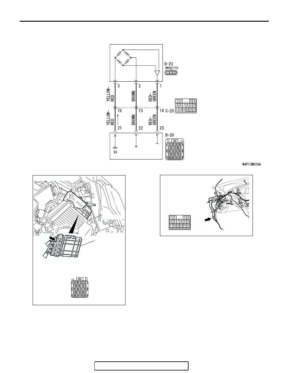
MULTIPORT FUEL INJECTION (MFI) DIAGNOSIS
TSB Revision
MULTIPORT FUEL INJECTION (MFI) <3.8L ENGINE>
13B-776
FUEL TANK
DIFFERENTIAL
PRESSURE
SENSOR
POWERTRAIN
CONTROL
MODULE
Fuel Tank Differential Pressure Sensor Circuit
AC306128
AC306248
B-20 HARNESS
CONNECTOR:
COMPONENT SIDE
AB
B-20
CONNECTOR: B-20
PCM
AIR
CLEANER
AC305231
CONNECTOR: C-25
AM
C-25