Mitsubishi Galant 9G. Manual - part 1062


  Index      Mitsubishi     Mitsubishi Galant 9G - service repair manual


Search            


Content   ..  1060  1061  1062  1063   ..


Mitsubishi Galant 9G. Manual - part 1062


MULTIPORT FUEL INJECTION (MFI) DIAGNOSIS

TSB Revision

MULTIPORT FUEL INJECTION (MFI) <3.8L ENGINE>

13B-548

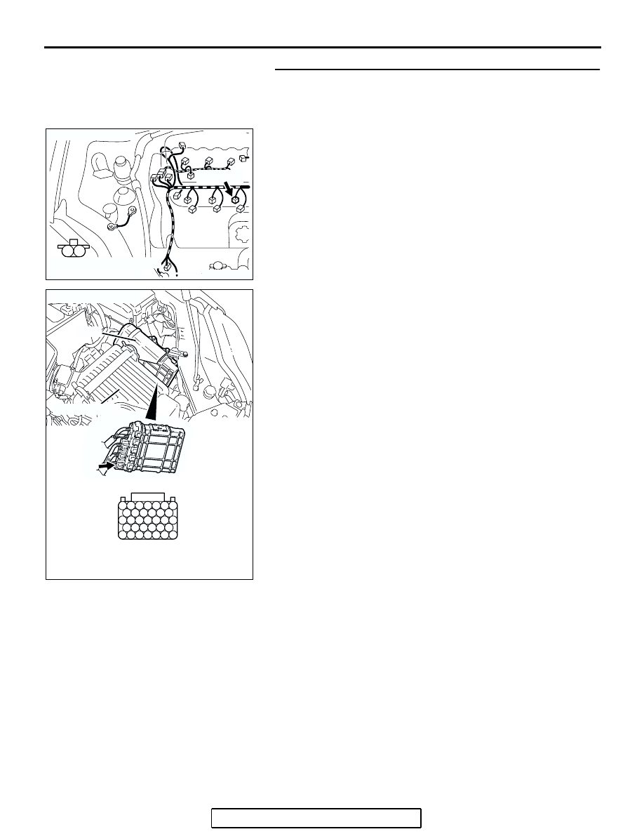
STEP 8. Check for open circuit and short circuit to ground 
and harness damage between No. 6 cylinder injector 
connector B-26 (terminal No. 2) and PCM connector B-23 
(terminal No. 127).
Q: Is the harness wire in good condition?

YES : Go to Step 9.
NO :  Repair it. Then go to Step 10.

AK303116

M

1

2

CONNECTOR: B-26

B-26 (GR)

HARNESS CONNECTOR:
COMPONENT SIDE

AB

127 126 125 124 123 122 121

133 132 131 130 129 128

140 139 138 137 136 135 134

146 145 144 143 142 141

153 152 151 150 149 148 147

AK303058

HARNESS CONNECTOR: 
COMPONENT SIDE

CONNECTOR: B-23

B-23

PCM

AB

AIR CLEANER

MULTIPORT FUEL INJECTION (MFI) DIAGNOSIS

TSB Revision

MULTIPORT FUEL INJECTION (MFI) <3.8L ENGINE>

13B-549

STEP 9. Using the oscilloscope, check the No. 6 cylinder 
injector.
(1) Disconnect the No. 6 cylinder injector connector B-26 and 

connect the test harness special tool (MB991658) between 
the separated connectors. (All terminals should be 
connected)

(2) Connect the oscilloscope probe to the injector side 

connector terminal No. 2.
NOTE: When measuring with the PCM side connector, dis-
connect the all PCM connectors and connect check har-
ness special tool (MB991923) between the separated 
connectors. Then connect an oscilloscope probe to the 
check harness connector terminal No. 127.

(3) Start the engine and run at idle.

(4) Measure the waveform.

• The waveform should show a normal pattern similar to 

the illustration.

(5) Turn the ignition switch to the "LOCK" (OFF) position.
Q: Is the waveform normal?

YES : It can be assumed that this malfunction is intermittent. 

Refer to GROUP 00, How to Use 
Troubleshooting/Inspection Service Points 

− How to 

Cope with Intermittent Malfunctions 

P.00-14

.

NO :  Replace the PCM. Then go to Step 10.

STEP 10. Test the OBD-II drive cycle.
(1) Carry out a test drive with the drive cycle pattern. Refer to 

Diagnostic Function 

− OBD-II Drive Cycle − Procedure 6 − 

Other Monitor 

P.13B-6

.

(2) Check the diagnostic trouble code (DTC).
Q: Is DTC P0206 set?

YES : Retry the troubleshooting.
NO :  The inspection is complete.

AK303116

M

1

2

CONNECTOR: B-26

B-26 (GR)

HARNESS CONNECTOR:
COMPONENT SIDE

AB

AK302166

1 2

INJECTOR
CONNECTOR

MB991658

OSCILLOSCOPE

AB

AKX01557 AB

A

NORMAL  WAVEFORM

A:INJECTOR DRIVE TIME

MULTIPORT FUEL INJECTION (MFI) DIAGNOSIS

TSB Revision

MULTIPORT FUEL INJECTION (MFI) <3.8L ENGINE>

13B-550

DTC P0222: Throttle Position Sensor (Sub) Circuit Low Input

CAUTION

If DTC P0222 has been set, TCL related DTC 
U1120 is also set. After P0222 has been diag-
nosed, don't forget to erase DTC U1120.

.

6

1 2 3 4 5

100

99

92

91

93 94 95

96 97 98

101 102 103 104

105 106 107 108

109 110 111 112 113

AK400888

YELLO

W

-RED

RED-WHITE

BLA

CK-WHITE

HALL IC

B-06

94

5

THROTTLE
POSITION
SENSOR 
(SUB)

POWERTRAIN 
CONTROL 
MODULE 
(PCM)

99

95

4

3

Throttle Position Sensor (sub) Circuit

B-22

5 V

AK303042

THROTTLE BODY ASSEMBLY
(INCORPORATING THROTTLE
POSITION SENSOR)

B-06 (B)

CONNECTOR: B-06

AB

AK303043

CONNECTOR: B-22

B-22 (B)

PCM

AB

AIR CLEANER

MULTIPORT FUEL INJECTION (MFI) DIAGNOSIS

TSB Revision

MULTIPORT FUEL INJECTION (MFI) <3.8L ENGINE>

13B-551

CIRCUIT OPERATION

• A 5-volt power supply is applied on the throttle 

position sensor (sub) power terminal (terminal 
No. 5) from the PCM (terminal No. 94).
The ground terminal (terminal No. 3) is grounded 
with PCM (terminal No. 95).

.

TECHNICAL DESCRIPTION

• The throttle position sensor (sub) outputs voltage 

which corresponds to the throttle valve opening 
angle.

• The PCM checks whether the voltage is within a 

specified range.

.

DESCRIPTIONS OF MONITOR METHODS

Throttle position sensor (sub) output voltage is out of 

specified range.

.

MONITOR EXECUTION

Continuous

.

MONITOR EXECUTION CONDITIONS 
(Other monitor and Sensor)

Other Monitor (There is no temporary DTC stored 

in memory for the item monitored below)

• Not applicable

Sensor (The sensor below is determined to be 

normal)

• Not applicable

.


Content   ..  1060  1061  1062  1063   ..