Mitsubishi Galant 9G. Manual - part 1052


  Index      Mitsubishi     Mitsubishi Galant 9G - service repair manual


Search            


Content   ..  1050  1051  1052  1053   ..


Mitsubishi Galant 9G. Manual - part 1052


MULTIPORT FUEL INJECTION (MFI) DIAGNOSIS

TSB Revision

MULTIPORT FUEL INJECTION (MFI) <3.8L ENGINE>

13B-508

DIAGNOSIS

Required Special Tools:

• MB991958: Scan Tool (MUT-III Sub Assembly)

• MB991824: V.C.I.

• MB991827: USB Cable

• MB991910: Main Harness A

• MB991658: Test Harness

• MB991923: Power Plant ECU Check Harness

STEP 1. Using scan tool MB991958, check actuator test 
item 03: No. 3 injector.

CAUTION

To prevent damage to scan tool MB991958, always turn the 
ignition switch to the "LOCK" (OFF) position before con-
necting or disconnecting scan tool MB991958.
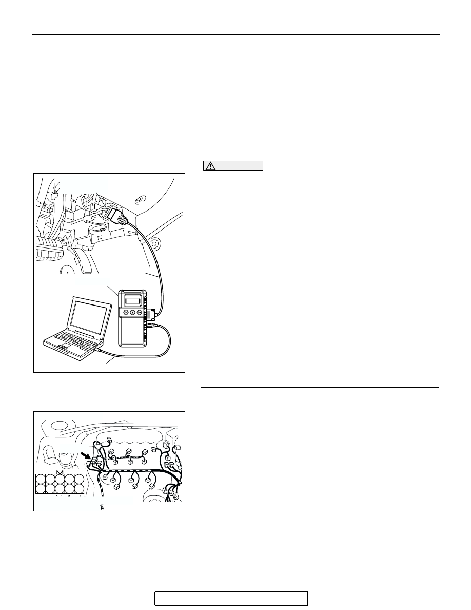
(1) Connect scan tool MB991958 to the data link connector.
(2) Start the engine and run at idle.
(3) Set scan tool MB991958 to the actuator testing mode for 

item 03, No. 3 injector.

(4) Warm up the engine to normal operating temperature: 80

°C 

to 95

°C (176°F to 203°F).

• The idle should become slightly rougher.

(5) Turn the ignition switch to the "LOCK" (OFF) position.
Q: Is the actuator operating properly?

YES : It can be assumed that this malfunction is intermittent. 

Refer to GROUP 00, How to Use 
Troubleshooting/Inspection Service Points 

− How to 

Cope with Intermittent Malfunctions 

P.00-14

.

NO :  Go to Step 2.

STEP 2. Check harness connector B-32 at intermediate 
connector for damage.
Q: Is the harness connector in good condition?

YES : Go to Step 3.
NO :  Repair or replace it. Refer to GROUP 00E, Harness 

Connector Inspection 

P.00E-2

. Then go to Step 12.

AC305412

AB

MB991910

DATA LINK

CONNECTOR

MB991824

MB991827

AK303053

3

4

5

8

9

1

2

6

7

10

CONNECTOR: B-32

HARNESS CONNECTOR:
COMPONENT SIDE

AB

B-32 (B)

MULTIPORT FUEL INJECTION (MFI) DIAGNOSIS

TSB Revision

MULTIPORT FUEL INJECTION (MFI) <3.8L ENGINE>

13B-509

STEP 3. Check the No. 3 cylinder injector resistance at 
intermediate connector B-32.
(1) Disconnect the intermediate connector B-32.

(2) Measure the resistance between terminal No. 9 and No. 10.

• Resistance should be between 10.5 and 13.5 ohms.

Q: Is the measured resistance between 10.5 and 13.5 

ohms?
YES : 
Go to Step 6.
NO :  Go to Step 4.

STEP 4. Check the connector B-03 at No. 3 cylinder 
injector for damage.
Remove the intake manifold.
Q: Is the harness connector in good condition?

YES : Go to Step 5.
NO :  Repair or replace it. Refer to GROUP 00E, Harness 

Connector Inspection 

P.00E-2

. Then go to Step 12.

AK303053

3

4

5

8

9

1

2

6

7

10

CONNECTOR: B-32

HARNESS CONNECTOR:
COMPONENT SIDE

AB

B-32 (B)

1

2 3

6

7 8

4 5

9 10

AK303107

B-32 
INTERMEDIATE
CONNECTOR

AB

AK303108

M

1

2

CONNECTOR: B-03

AB

B-03 (GR)

HARNESS CONNECTOR:
COMPONENT SIDE

MULTIPORT FUEL INJECTION (MFI) DIAGNOSIS

TSB Revision

MULTIPORT FUEL INJECTION (MFI) <3.8L ENGINE>

13B-510

STEP 5. Check the No. 3 cylinder injector.
(1) Disconnect the No. 3 cylinder injector connector B-03.

(2) Measure the resistance between injector side connector 

terminal No. 1 and No. 2.

Standard value: 10.5 

 13.5 ohms [at 20°C (68°F)]

Q: Is the measured resistance between 10.5 and 13.5 ohms 

[at 20

°C (68°F)]?

YES : Repair harness wire between intermediate connector 

B-32 (terminal No. 9) and injector connector B-03 
(terminal No. 1) and harness wire between No.3 
cylinder injector connector B-03 (terminal No. 2) 
and intermediate connector B-32 (terminal No. 10) 
because of open circuit or short circuit to ground 
or harness damage.

Then go to Step 12.

NO :  Replace the No.3 cylinder injector. Then go to Step 

12.

AK303108

M

1

2

CONNECTOR: B-03

AB

B-03 (GR)

HARNESS CONNECTOR:
COMPONENT SIDE

AK000559

2

1

INJECTOR SIDE
CONNECTOR

AB

MULTIPORT FUEL INJECTION (MFI) DIAGNOSIS

TSB Revision

MULTIPORT FUEL INJECTION (MFI) <3.8L ENGINE>

13B-511

STEP 6. Measure the power supply voltage at intermediate 
connector B-32.
(1) Disconnect the connector B-32 and measure at the female 

connector side.

(2) Turn the ignition switch to the "ON" position.

(3) Measure the voltage between terminal No. 9 and ground.

• Voltage should be battery positive voltage.

(4) Turn the ignition switch to the "LOCK" (OFF) position.
Q: Is battery positive voltage (approximately 12 volts) 

present?
YES : 
Go to Step 8.
NO :  Go to Step 7.

STEP 7. Check harness connector B-17X at MFI relay for 
damage.
Q: Is the harness connector in good condition?

YES : Repair harness wire between MFI relay connector 

B-17X (terminal No. 4) and intermediate connector 
B-32 (terminal No. 9) because of open circuit or short 
circuit to ground. Then go to Step 12.

NO :  Repair or replace it. Refer to GROUP 00E, Harness 

Connector Inspection 

P.00E-2

. Then go to Step 12.

AK303053

3

4

5

8

9

1

2

6

7

10

CONNECTOR: B-32

HARNESS CONNECTOR:
COMPONENT SIDE

AB

B-32 (B)

3

4

5

8

9

1

2

6

7

10

AK203172

B-32 HARNESS 
CONNECTOR: 
COMPONENT
SIDE

AB

1

2

3

4

AK303017

CONNECTOR: B-17X

FRONT OF VEHICLE

B-17X

AB

HARNESS
CONNECTOR:
COMPONENT SIDE

RELAY BOX


Content   ..  1050  1051  1052  1053   ..