Content .. 1041 1042 1043 1044 ..
Mitsubishi Galant 9G. Manual - part 1043
MULTIPORT FUEL INJECTION (MFI) DIAGNOSIS
TSB Revision
MULTIPORT FUEL INJECTION (MFI) <3.8L ENGINE>
13B-472
DTC SET CONDITIONS
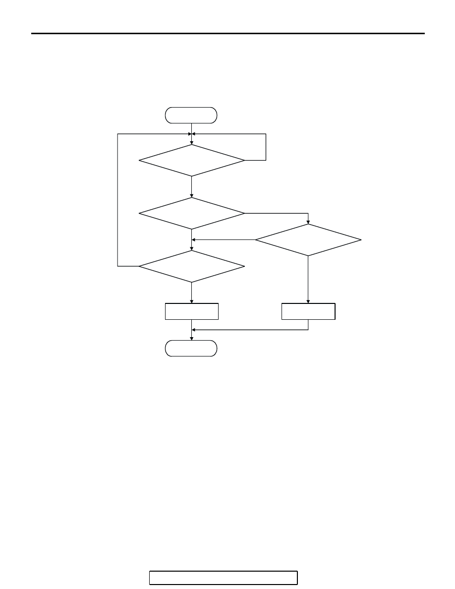
Logic Flow Chart
.
Check Conditions
• 2 seconds or more have passed since the engine
starting sequence was completed.
Judgement Criteria
• Sensor output voltage has continued to be 4.6
volts or higher for 2 seconds.
.
OBD-II DRIVE CYCLE PATTERN
Refer to Diagnostic Function
− OBD-II Drive Cycle −
Procedure 6
.
.
TROUBLESHOOTING HINTS (The most
likely causes for this code to be set are: )
• Fuel tank temperature sensor failed.
• Open fuel tank temperature sensor circuit, har-
ness damage, or connector damage.
• PCM failed.
START
MONITORING
CONDITIONS
END
NO
NO
NO
YES
YES
YES
MALFUNCTION
GOOD
OUTPUT VOLTAGE
< 0.1V
CONTINUOUS
FAILURE FOR 2secs
OUTPUT VOLTAGE
> 4.6V
NO
YES
AK302403