Mitsubishi Galant 9G. Manual - part 93
SYMPTOM PROCEDURES
TSB Revision
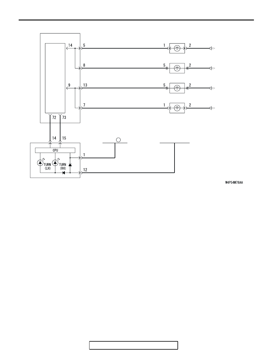
SIMPLIFIED WIRING SYSTEM (SWS)
54B-368
JUNCTION BLOCK
22
RELAY BOX
(FUSE )
ETACS-
ECU
FRONT COMBINATION
LIGHT (LH)
REAR COMBINATION
LIGHT (LH)
REAR COMBINATION
LIGHT (RH)
FRONT COMBINATION
LIGHT (RH)
IGNITION
SWITCH (IG1)