Mitsubishi Galant 9G. Manual - part 11
DIAGNOSTIC TROUBLE CODE PROCEDURES
TSB Revision
SIMPLIFIED WIRING SYSTEM (SWS)
54B-40
DTC 010: Bus Off
CAUTION
If DTC 010 is set in the ETACS-ECU, always diag-
nose the CAN main bus line.
CAUTION
If the DTC is set as past trouble, the ECU cannot
be defective. Do not replace it.
.
TROUBLE JUDGMENT
DTC 010 will be stored when the ETACS-ECU
ceases CAN communication (bus off) and then
resumes the communication by turning the ignition
switch to the "LOCK" (OFF) position
.
TECHNICAL DESCRIPTION (COMMENT)
Carry out diagnosis with particular emphasis on wir-
ing and connector(s) in the CAN bus lines. For diag-
nosis procedures, refer to "How to cope with past
trouble" (Refer to GROUP 00, How to treat past trou-
ble
.
TROUBLESHOOTING HINTS
• The wiring harness or connectors may have
loose, corroded, or damaged terminals, or termi-
nals pushed back in the connector.
DIAGNOSIS
Required Special Tools:
• MB991223: Harness Set
• MB991958: Scan Tool (MUT-III Sub Assembly)
• MB991824: Vehicle Communication Interface (V.C.I.)
• MB991827: MUT-III USB Cable
• MB991910: MUT-III Main Harness A
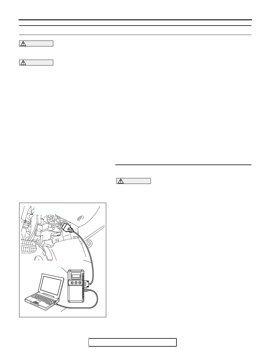
STEP 1. Using scan tool MB991958, diagnose the CAN bus
line.
CAUTION
To prevent damage to scan tool MB991958, always turn the
ignition switch to the "LOCK" (OFF) position before con-
necting or disconnecting scan tool MB991958.
(1) Connect scan tool MB991958. Refer to "How to connect
."
(2) Turn the ignition switch to the "ON" position.
(3) Diagnose the CAN bus line.
(4) Turn the ignition switch to the "LOCK" (OFF) position.
Q: Is the CAN bus line found to be normal?
YES : Go to Step 2.
NO : Repair the CAN bus line (Refer to GROUP 54C,
AC305412
AB
MB991910
DATA LINK
CONNECTOR
MB991824
MB991827