Mitsubishi Galant 9G. Manual - part 4
SWS DIAGNOSIS
TSB Revision
SIMPLIFIED WIRING SYSTEM (SWS)
54B-12
HOW TO DIAGNOSE THE CAN BUS LINES
Required Special Tools:
• MB991958: Scan Tool (MUT-III Sub Assembly)
• MB991824: Vehicle Communication Interface (V.C.I.)
• MB991827: MUT-III USB Cable
• MB991910: MUT-III Main Harness A
CAUTION
To prevent damage to scan tool MB991958, always turn the
ignition switch to the "LOCK" (OFF) position before con-
necting or disconnecting scan tool MB991958.
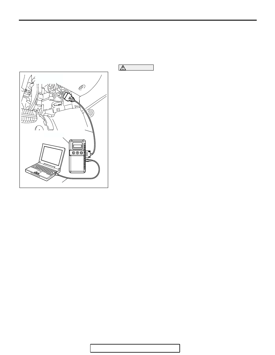
1. Connect scan tool MB991958 to the data link connector.
2. Turn the ignition switch to the "ON" position.
3. Select "CAN bus diagnosis" from the start-up screen.
4. When the vehicle information is displayed, confirm that it
matches the vehicle being diagnosed.
• If they match, go to step 8.
• If not, go to step 5.
5. Select the "view vehicle information" button.
6. Enter the vehicle information and select the "OK" button.
7. When the vehicle information is displayed, confirm again
that it matches the vehicle being diagnosed.
• If they match, go to step 8.
• If not, go to step 5.
8. Select the "OK" button.
9. When the optional equipment screen is displayed, choose
the one which the vehicle is fitted with, and then select the
"OK" button.
SWS DIAGNOSTIC TROUBLESHOOTING STRATEGY
M1549000500906
1. Gather information about the problem from the
customer.
2. Verify that the condition described by the
customer exists.
NOTE: If an error occurs in the SWS communica-
tion line, the ECU isolated from the communica-
tion line performs a fail-safe or backup operation,
so the problem may not match the one shown in
the Trouble Symptom Chart. However, the cause
of the failure can be tracked down by performing
the following troubleshooting with the SWS moni-
tor.
3. Version number and destination check
Check whether the SWS version number (1) and
destination (North America) meet the vehicle
specifications. If they are different, replace the
ETACS-ECU with a correct one.
4. Use scan tool MB991958 (MUT-III Sub Assembly)
to select "ECU COMM Check" on the SWS
monitor display.
Check whether the communication status of the
input- or output-signal-side ECU associated with
the defective function is normal.
• If "OK" is displayed for all related ECUs, they
communicate with each other normally and the
input or output signal circuit system may be
defective. Therefore, check SWS monitor service
data.
• If "NG" is displayed for any of the related ECUs,
something may be wrong with the ECU for which
"NG" appears, its power supply or grounding sys-
tem, or a wiring harness or connector between
the SWS monitor and the ECU. Check the wiring
harness and connectors associated with the ECU
and examine the ECU itself.
5. Service data on the SWS monitor
Select the defective function from the
function-specific diagnostic menu, and check the
service data that appears for each function item.
AC305412
AB
MB991910
DATA LINK
CONNECTOR
MB991824
MB991827