Mitsubishi Pajero Pinin. Manual - part 361


  Index      Mitsubishi     Mitsubishi Pajero Pinin - service repair manual 2001 year


Search            


Content   ..  359  360  361  362   ..


Mitsubishi Pajero Pinin. Manual - part 361


SWS – 

Troubleshooting

54B-46

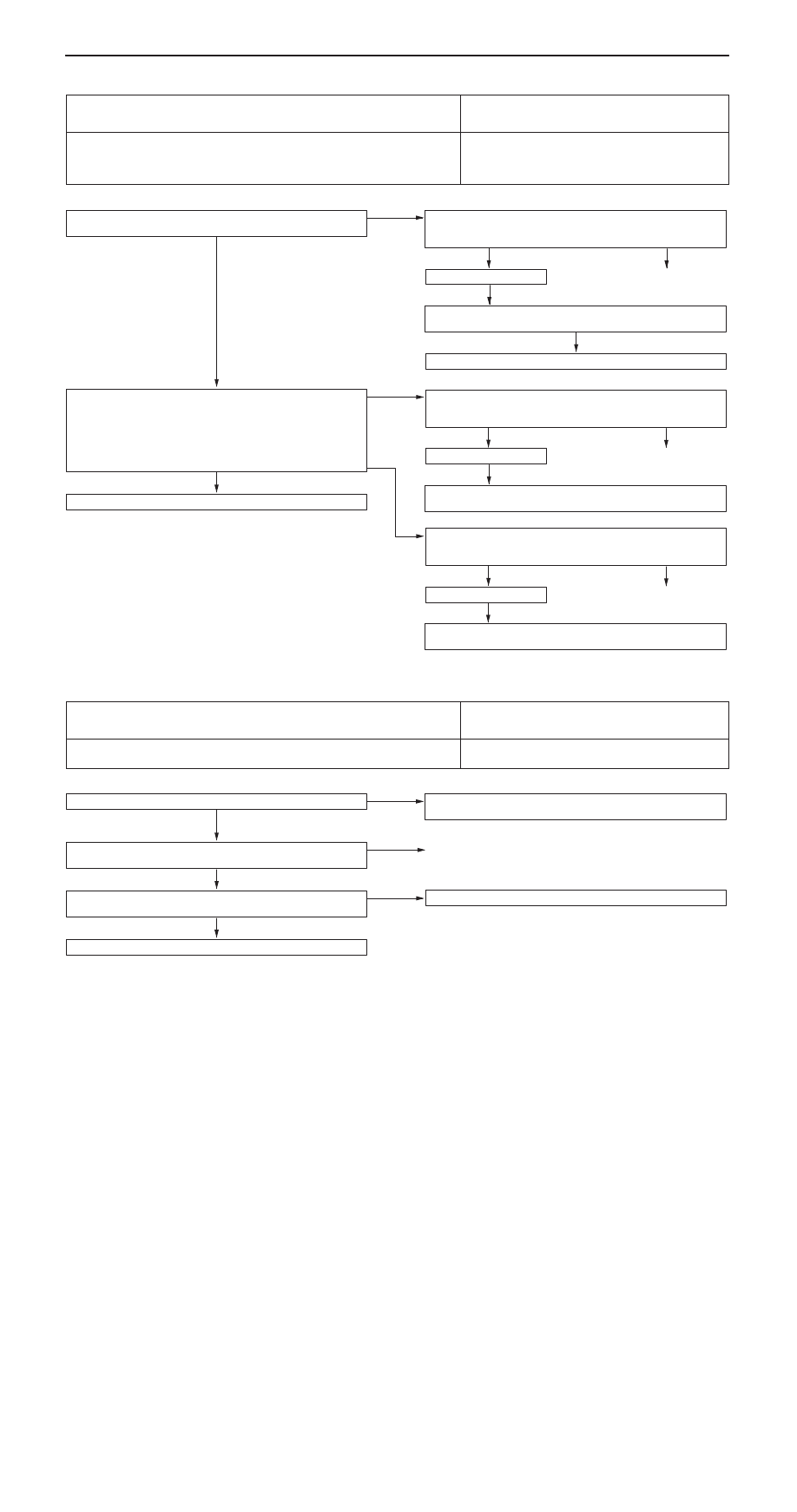
Inspection Procedure N-16

Power window main switch: Any switch signal is not sent
to the ETACS-ECU.

Probable cause

If there is a problem with communication between the power window main
switch and the ETACS-ECU, the input signal check for the power window main
switch can no longer be carried out. In addition, the power window timer function
will also stop working.

D

Malfunction of power window main switch

D

Malfunction of ETACS-ECU

D

Malfunction of harness wire or connector

Can the driver’s side power window be operated by the power
window main switch?

Yes

Check the following connectors:
<L.H. drive vehicles> C-02, C-45, C-83, E-10
<R.H. drive vehicles> C-02, C-21, C-83, E-10

OK

Check trouble symptoms.

NG

Repair

NG

Check the harness wire between power window main switch and
ETACS-ECU.

OK

Replace the power window main switch or ETACS-ECU.

No

Measure at power window main switch connector E-10.

D

Disconnect connector and measure at harness side.

D

Turn the ignition switch to ON position.

(1) Voltage between terminal 1 and body earth.

OK: System voltage

(2) Continuity between terminal 5 and body earth.

OK: Continuity

(1) NG

Check the following connectors:
<L.H. drive vehicles> C-45, C-71, C-74, E-10
<R.H. drive vehicles> C-21, C-71, C-74, E-10

OK

Check trouble symptoms.

NG

Repair

NG

Check the harness wire between power window main switch and
power window relay.

OK

Replace the power window main switch.

(2) NG

Check the following connectors:
<L.H. drive vehicles> C-45, E-10
<R.H. drive vehicles> C-21, E-10

OK

Check trouble symptoms.

NG

Repair

NG

Check the harness wire between power window main switch and
body earth.

Inspection Procedure N-17

Transmitter: Any switch signal is not sent to the
ETACS-ECU.

Probable cause

The transmitter input signal is used to operate the keyless entry system. If the
signal fails, keyless entry will not work normally.

D

Malfunction of transmitter

D

Malfunction of ETACS-ECU

Has the encrypted code been registered properly?

No

Re-register the encrypted code. (Refer to GROUP 42 – Keyless
Entry System.)

Yes

Check the transmitter battery. (Refer to GROUP 42 – Keyless Entry
System.)

NG

Replace

OK

Use an other transmitter to register the secret code. (Refer to
GROUP 42 – Keyless Entry System.)

NG

Replace the ETACS-ECU.

OK

Replace the defective transmitter.

SWS – 

Troubleshooting

54B-47

Inspection Procedure N-18

Multi-center display: Any switch signal is not sent to the
ETACS-ECU.

Probable cause

The cause is probably a malfunction of the multi-center display or the
ETACS-ECU.

D

Malfunction of multi-center display

D

Malfunction of ETACS-ECU

D

Malfunction of harness wire or connector.

Is the multi-center display operated normally?

No

Carry out troubleshooting for the multi-center display. (Refer to
GROUP 54A – Multi-center Display.)

OK

Replace the multi-center display or ETACS-ECU.

Yes

Check the following connectors:
C-02, C-53, C-83

NG

Repair

OK

Check trouble symptoms.

NG

Check the harness wire between multi-center display and ETACS-
ECU.

NG

Repair

Inspection Procedure O-1

Check the circuit (power supply line) from the battery to
the ETACS-ECU.

Probable cause

If that power supply circuit is defective, the circuit flowing trough the ignition
switch (IG1) will function as a back-up circuit. In this case, the following
functions will not work when the ignition switch is at LOCK (OFF) position.

D

Light reminder alarm function

D

Central door lock ing system

D

Hazard warning lamp

D

Room lamp

D

Malfunction of ETACS-ECU

D

Malfunction of harness wire or connector.

Measure at ETACS-ECU connector C-82.

D

Disconnect connector and measure at J/B side.

D

Voltage between terminal 6 and body earth.
OK: System voltage

NG

Check the following connectors:
C-72, C-82

OK

Check trouble symptoms.

NG

Repair

NG

Check the harness wire between ETACS-ECU and fusible link
(3).

OK

Replace the ETACS-ECU.

NOTES

SWS  – 

General/Troubleshooting

54B-1

GROUP 54B

SMART WIRING SYSTEM(SWS)

GENERAL

OUTLINE OF CHANGES


Due to the introduction of 5-door models, the troubleshooting for the rear power windows have been
added. 

TROUBLESHOOTING

TROUBLE SYMPTOM CHART

Trouble symptom

Inspection 
procedure

Reference 
page

Power window

Rear power window sub-switches can not operate rear door
windows. (However, power window main switch can operate rear
door windows.)

D-9

54B-2


Content   ..  359  360  361  362   ..