Mitsubishi Pajero Pinin. Manual - part 311


  Index      Mitsubishi     Mitsubishi Pajero Pinin - service repair manual 2001 year


Search            


Content   ..  309  310  311  312   ..


Mitsubishi Pajero Pinin. Manual - part 311


SRS – 

SRS Maintenance

52B-23

SRS MAINTENANCE

The SRS must be inspected by an authorized dealer 10 years
after the date of vehicle registration.

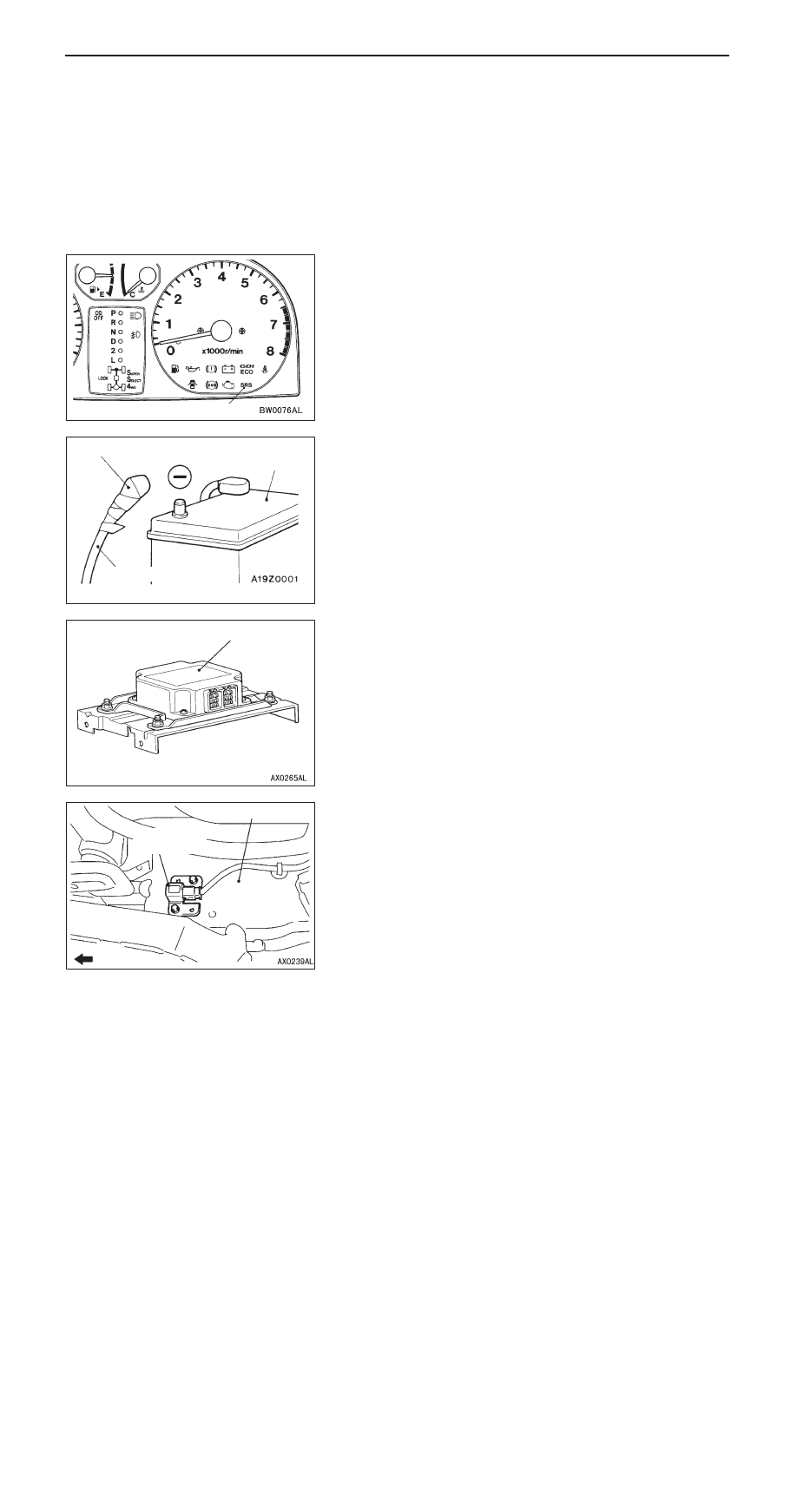
SRS WARNING LAMP CHECK

Turn the ignition switch to the “ON” position. Does the SRS
warning lamp illuminate for about 7 seconds, turn off and
then remain extinguished for at least 5 seconds? If yes, SRS
system is functioning properly. If no, consult page 52B-8.

SRS COMPONENT VISUAL CHECK

Turn the ignition key to LOCK (OFF) position, disconnect the
negative battery cable and tape the terminal.

Caution
Wait at least 60 seconds after disconnecting the battery
cable before doing any further work. (Refer to P.52B-4.)

SRS CONTROL UNIT (SRS-ECU)
1.

Check SRS-ECU case and brackets for dents, cracks,
deformation or rust.
Caution
The SRS may not activate if the SRS-ECU is not
installed properly, which could result in serious injury
or death to the vehicle’s driver or front passenger.

2.

Check connector for damage, and terminals for
deformation or rust.
Replace SRS-ECU if it fails visual check. 
(Refer to P.52B-34.)

FRONT IMPACT SENSORS

1.

Check the front side member for deformation or rest.

2.

Check the front impact sensor for dents, cracks,
deformation or rust.

3.

Check the sensor harnesses for binding, the connectors
for damage, and the terminals for deformation.

SRS warning lamp

Battery (–) cable

Insulating tape

Battery

SRS-ECU

Front side member

Front impact
sensor

Forward

SRS – 

SRS Maintenance

52B-24

AIR BAG MODULES, STEERING WHEEL AND CLOCK
SPRING

1.

Remove the air bag modules, steering wheel and clock
spring. (Refer to P.52B-36.)

Caution
The removed air bag modules should be stored in
a clean, dry place with the cover face up.

2.

Check cover for dents, cracks or deformation.

3.

Check connector for damage, terminals deformities, and
harness for binds.

4.

Check air bag inflator case for dents, cracks or deformities.

5.

Check harness and connectors for damage, and terminals
for deformation.

6.

Check clock spring connectors and protective tube for
damage, and terminals for deformation.

7.

Visually check the clock spring case for damage.

8.

Align the mating marks of the clock spring and, after turning
the vehicle’s front wheels to straight-ahead position, install
the clock spring to the column switch.

Mating Mark Alignment

Turn the clock spring clockwise fully, and then turn back
it approx. 3 times counterclockwise to align the mating
marks.

Caution
If the clock spring’s mating mark is not properly
aligned, the steering wheel may not be completely
rotational during a turn, or the flat cable within the
clock spring may be severed, obstructing normal
operation of the SRS and possibly leading to serious
injury to the vehicle’s driver or front passenger.

9.

Install the steering column covers, steering wheel and
the air bag module.

10. Check steering wheel for noise, binds of difficult operation.

Connector

<Driver’s side>

<Front passenger’s side>

Inflator case

Connector

Inflator case

Protective tubes

Mating
marks

Case

SRS – 

SRS Maintenance

52B-25

11. Check steering wheel for excessive free play.

REPLACE ANY VISUALLY INSPECTED PART IF IT FAILS
THAT INSPECTION. (Refer to P.52B-41.)

Caution
The SRS may not activate if any of the above
components is not installed properly, which could
result in serious injury or death to the vehicle’s driver
or front passenger.

FRONT SEAT BACK ASSEMBLY (SIDE AIR BAG
MODULE)

1.

Check that there is no abnormality in the seat air bag
module deployment section.

2.

Check that there is no connector damage, bent terminals
or clamping of the harness.

SIDE IMPACT SENSORS

1.

Check that there is no bending or corrosion in the quarter
panel, inner.

2.

Check that there is no denting, breakage, bending or
corrosion of the side impact sensor.

3.

Check that there is no clamping of the harness, connector
damage or bent terminals.

NOTE
The illustration at left shows the side impact sensor (R.H.).
The position of the side impact sensor (L.H.) is symmetrical
to this.

Caution
The SRS may not activate if the side impact sensors
are not installed properly, which could result in serious
injury or death to the vehicle’s driver or front
passenger.

Side air bag module
deployment section

Quarter
panel,
inner

Side
impact
sensor

SRS – 

SRS Maintenance

52B-26

INSTRUMENT PANEL WIRING HARNESS/FRONT WIRING HARNESS/ASSIST
WIRING HARNESS/BODY WIRING HARNESS

Instrument panel wiring harness

Body wiring harness

Front wiring harness

1.

Check connector for poor connection.

2.

Check harnesses for binds, connectors for damage, and
terminals for deformation.
REPLACE ANY CONNECTORS OR HARNESS THAT
FAIL THE VISUAL INSPECTION. (Refer to P.52B-4.)

Caution
The SRS may not activate if SRS harnesses or
connectors are damaged or improperly connected,
which could result in serious injury or death to the
vehicle’s driver or front passenger.

POST-INSTALLATION INSPECTION

Reconnect the negative battery terminal. Turn the ignition
switch to the “ON” position. Does the SRS warning lamp
illuminate for about 7 seconds, turn off and then remain
extinguished for at least 5 seconds? If yes, SRS system is
functioning properly. If no, consult page 52B-8.

SRS warning lamp


Content   ..  309  310  311  312   ..