Mitsubishi Pajero Pinin. Manual - part 219
REAR AXLE –
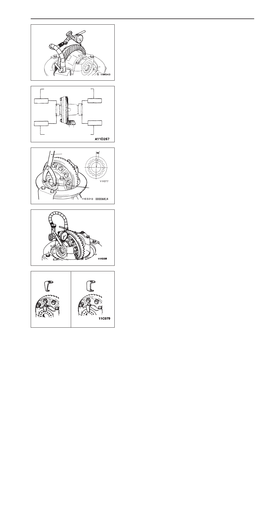
Differential Carrier
27-26
2.
With the drive pinion locked in place, measure the drive
gear backlash with a dial indicator on the drive gear.
NOTE
Measure at four points or more on the circumference of
the drive gear.
Standard value: 0.08 – 0.13 mm
3.
If the drive gear backlash is not within the standard value,
use the special tools (MB991367 and MB991385) to tighten
or loosen the side bearing nuts as shown in the illustration,
in order to adjust the backlash.
NOTE
First loosen the side bearing nut, then tighten the side
bearing nut the same amount as when it was loosened.
4.
Use the special tools to turn down both right and left side
bearing nuts on half the distance between centres of two
neighboring holes, in order to apply the preload to the
side bearing.
5.
Measure the drive gear runout at the shoulder on the
reverse side of the drive gear.
Limit: 0.05 mm
6.
If the drive gear runout exceeds the limit, reinstall by
changing the phase of the drive gear and differential case,
and remeasure.
7.
If adjustment is not possible, replace the differential case
or limited slip differential case, or replace the drive gear
and drive pinion as a set.
8.
Select either of the lock plates, and then install it.
9.
Check the drive gear tooth contact. If poor contact is
evident, adjust the drive gear tooth contact. (Refer to
GROUP 26 – Differential carrier.)
Loosen
If backlash is too small
Tighten
If backlash is too large
Tighten
Loosen
MB991367
MB991385
MB092153
MB092154