Mitsubishi Pajero Pinin. Manual - part 205


  Index      Mitsubishi     Mitsubishi Pajero Pinin - service repair manual 2001 year


Search            


Content   ..  203  204  205  206   ..


Mitsubishi Pajero Pinin. Manual - part 205


FRONT AXLE – 

Differential Carrier

26-39

"

E

A

DRIVE PINION ROTATION TORQUE
ADJUSTMENT

Adjust the drive pinion rotation torque by using the following
procedure:

1.

Insert the drive pinion into the gear carrier, and then install
the drive pinion spacer, the drive pinion rear shim, the
drive pinion rear bearing inner race, and the companion
flange in that order.

NOTE
Do not install the oil seal.
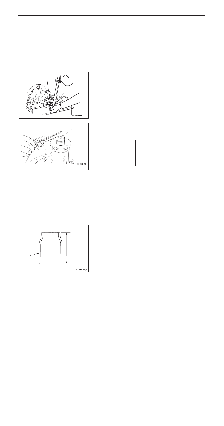
2.

Use the special tool to hold companion flange, and then
tighten the self-locking nut to the specified torque.

3.

Measure the drive pinion rotation torque (without the oil
seal) by using the special tool.

Standard value:

Bearing division

Bearing lubrication

Rotation torque Nm

New

None (With
anti-rust agent)

0.88 – 1.17*

1


0.29 – 0.49*

2

New/reused

Gear oil applied

0.39 – 0.49*

1


0.147 – 0.245*

2

NOTE
*

1

: A/T

*

2

: M/T

4.

If the drive pinion rotation torque is not within the range
of the standard value, adjust it by replacing the drive
pinion rear shim(s) or the drive pinion spacer.

NOTE
When selecting the drive pinion rear shims, if the number
of shims is large, reduce the number of shims to a minimum
by selecting the drive pinion spacers. Also, select the
drive pinion spacer from the following two types.

186 Nm

MB990850

MB990326

Identification
colour

A

FRONT AXLE – 

Differential Carrier

26-40

Drive pinion spacer
height (A) mm

Identification colour

46.67*

1

White

47.01*

1

57.72*

2

57.08*

2

Red

NOTE
*

1

: M/T

*

2

: A/T

5.

Remove the companion flange and drive pinion again.
Then, after inserting the drive pinion rear bearing inner
race into the gear carrier, use the special tool to press-fit
the oil seal.

6.

Install the drive pinion assembly and companion flange
with mating marks properly aligned, and use the special
tool to hold the companion flange, and then tighten the
self-locking nut to the specified torque.

7.

Measure the drive pinion rotation torque (with the oil seal)
by using the special tool.

Standard value:

Bearing division

Bearing lubrication

Rotation torque Nm

New

None (With
anti-rust agent)

0.98 – 1.27*

1


0.49 – 0.69*

2

New/reused

Gear oil applied

0.49 – 0.58*

1


0.343 – 0.441*

2

NOTE
*

1

: A/T

*

2

: M/T

8.

If the drive pinion rotation torque is not within the standard
value, check the tightening torque of the companion flange
self-locking nut and the oil seal installation condition.

MB990727

186 Nm

MB990850

MB990326

FRONT AXLE – 

Differential Carrier

26-41

"

F

A

DIFFERENTIAL GEAR BACKLASH ADJUSTMENT

Follow the procedures below to adjust the differential gear
backlash.
1.

Assemble the side gears, side gear spacers, pinion gears
and pinion washers into the differential case.

2.

Temporarily install the pinion shaft.

NOTE
Do not drive in the lock pin yet.

3.

Insert a wedge between the side gear and the pinion
shaft to lock the side gear.

4.

Measure the differential gear backlash with a dial indicator
on the pinion gear.

Standard value: 0 – 0.076 mm

Limit: 0.2 mm

Repeat the steps above for the other pinion gear.

5.

If the differential gear backlash exceeds the limit, adjust
the backlash by changing the side gear spacers.

6.

If adjustment is not possible, replace the side gears and
pinion gears as a set.

7.

Confirm that the differential gear backlash is correct, and
that the differential gear turns smoothly.

"

G

A

LOCK PIN INSTALLATION

1.

Align the pinion shaft lock pin hole with the differential
case lock pin hole, and drive in the lock pin.

2.

Stake the lock pin with a punch at two points.

"

H

A

DRIVE GEAR INSTALLATION

1.

Clean the drive gear attaching bolts.

2.

Remove the adhesive adhered to the threaded holes
of the drive gear by turning a tap (M10 x 1.25), and then
clean the threaded holes by applying compressed air.

Wedge

Side gear
thrust spacer

Side gear
thrust spacer

M10 


 1.25 (pitch)

FRONT AXLE – 

Differential Carrier

26-42

3.

Clean the drive gear attaching surface, and then apply
the specified adhesive to the threaded holes of the drive
gear.

Specified sealant:

3M Stud Locking 4170 or equivalent

4.

Install the drive gear onto the differential case with the
mating marks properly aligned.

5.

Tighten the drive gear attaching bolts provisionally, and
then tighten them to the specified torque in a diagonal
sequence.

Tightening torque: 78 – 88 Nm

"

I

A

SIDE BEARING INNER RACE INSTALLATION

Use the special tool to press the side bearing inner race
into the differential case.

"

J

A

DRIVE GEAR BACKLASH ADJUSTMENT

Adjust the drive gear backlash by the following procedures:
1.

Install the side bearing spacers, which are thinner than
those removed, to the side bearing outer races, and then
mount the differential case assembly into the gear carrier.

NOTE
Select side bearing spacers with the same thickness for
both the drive gear sides.

2.

Push the differential case assembly to one side, and
measure the clearance between the gear carrier and the
side bearing spacer with a thickness gauge.

Metal

MB990829

Metal

MB990829


Content   ..  203  204  205  206   ..