Mitsubishi Pajero Pinin. Manual - part 201
FRONT AXLE
–
Drive Shaft
26-23
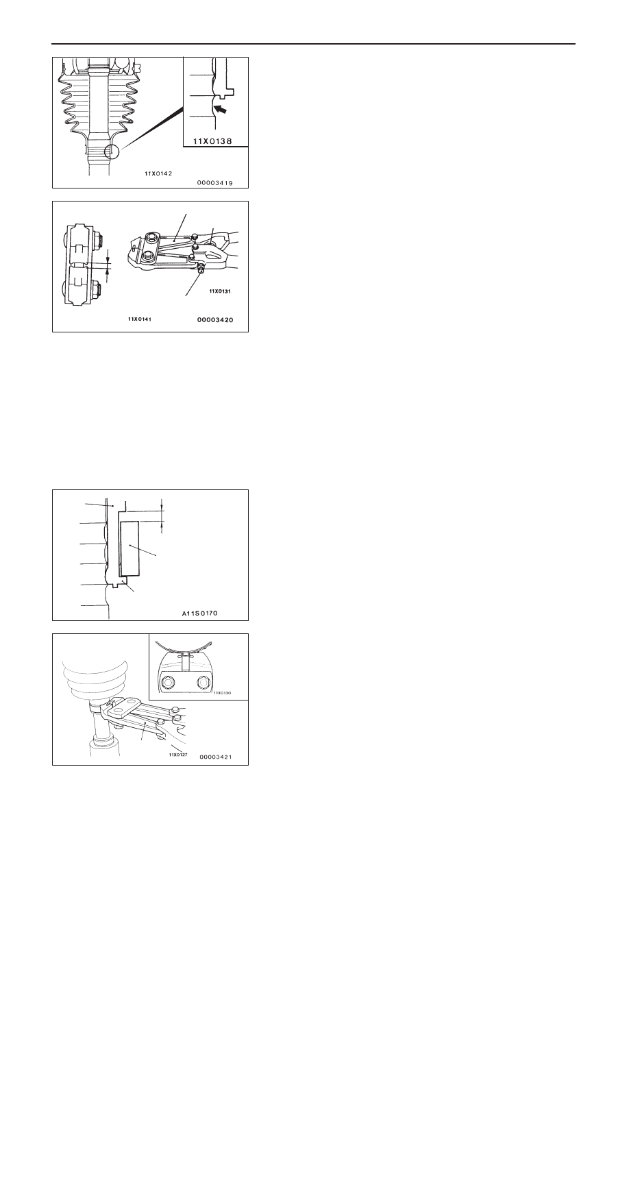
3.
Position the plastic boot small end so that one drive shaft
groove is visible.
4.
Turn the adjusting bolt of the special tool so that the
opening distance (W) meets the standard value.
Standard value (W):
2.9
mm
<More than 2.9
mm>
Tighten the adjusting bolt.
<Less than 2.9
mm>
Loosen the adjusting bolt
NOTE
(1) Turning the adjusting bolt changes the opening
distance (W) by approx. 0.7 mm.
(2) Do not turn the adjusting bolt more than one turn.
5.
Butt the boot band (small) against the boot end projection
so that a certain clearance (A) is obtained.
6.
Use the special tool to crimp the boot band (small).
Caution
(1) Secure the drive shaft in an upright position and
clamp the part of the B.J. boot band to be crimped
securely in the jaws of the special tool.
(2) Crimp the B.J. boot band until the special tool
stopper closes.
(W)
MB991561
Stopper
Adjusting bolt
Boot
Boot band (small)
Projection
A
MB991561