Mitsubishi Pajero Pinin. Manual - part 181


  Index      Mitsubishi     Mitsubishi Pajero Pinin - service repair manual 2001 year


Search            


Content   ..  179  180  181  182   ..


Mitsubishi Pajero Pinin. Manual - part 181


AUTOMATIC TRANSMISSION – 

On-vehicle Service

23-34

ON-VEHICLE SERVICE

ESSENTIAL SERVICE

AUTOMATIC TRANSMISSION FLUID CHECK

Caution
When the transmission has been replaced or overhauled,
or driving has been carried out under the severe condition,
the A/T fluid cooler line flushing should always be carried
out and also, the A/T fluid should always be replaced.

1.

Drive the vehicle until the A/T fluid temperature rises to
the normal temperature (70 – 90

_

C).

2.

Park the vehicle on a level surface.

3.

Move the selector lever through all positions to fill the
torque converter and the hydraulic circuits with A/T fluid,
and then move the selector lever to the N position.

4.

After wiping off any dirt around the oil level gauge, remove
the oil level gauge and check the condition of the A/T
fluid.

NOTE
If the A/T fluid smells as if it is burning, it means that
the A/T fluid has been contaminated by the particles from
the bushes and friction materials, a transmission overhaul
and flushing the A/T fluid cooler line may be necessary.

5.

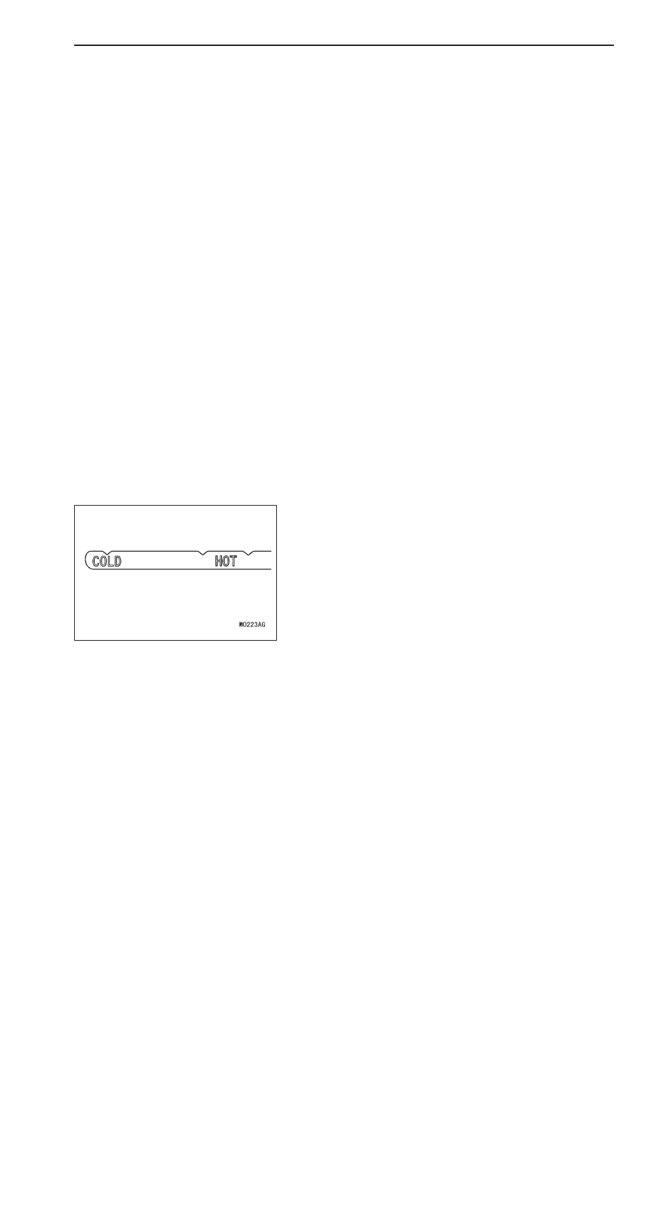
Check that the A/T fluid level is at the HOT mark on the
oil level gauge. If the A/T fluid level is lower than this,
pour in more A/T fluid until the level reaches the HOT
mark.

Automatic transmission fluid:

DEXRON 

II

 or equivalent

NOTE
If the A/T fluid level is low, the oil pump will draw in air
along with the A/T fluid, which will cause bubbles to form
inside the hydraulic circuit. This will in turn cause the
hydraulic pressure to drop, which will result in late shifting
and slipping of the clutches and brakes.
If there is too much A/T fluid, the gears can churn it up
into foam and cause the same conditions that can occur
with low A/T fluid levels.
In either case, air bubbles can cause overheating and
oxidation of the A/T fluid which can interfere with normal
valve, clutch, and brake operation. Foaming can also result
in A/T fluid escaping from the transmission vent hole, in
which case it may be mistaken for a leak.

6.

Securely insert the oil level gauge.

AUTOMATIC TRANSMISSION – 

On-vehicle Service

23-35

AUTOMATIC TRANSMISSION FLUID REPLACEMENT

Caution
When the transmission has been replaced or overhauled,
the A/T fluid cooler line flushing should always be carried
out before installing the A/T fluid cooler hose.

If you have a A/T fluid changer, use this changer to replace
the A/T fluid. If you do not have a A/T fluid changer, replace
the A/T fluid by the following procedure.
1.

Disconnect the hose shown in the illustration which
connects the transmission and the A/T fluid cooler (inside
the radiator).

2.

Start the engine and let the A/T fluid drain out.

Running conditions: N range with engine idling

Caution
The engine should be stopped within one minute after
it is started. If the A/T fluid has all drained out before
then, the engine should be stopped at that point.

Discharge volume: Approx. 3.4 

3.

Remove the drain plug from the bottom of the transmission
case to drain the A/T fluid.

Discharge volume: Approx. 0.8 

4.

Install the drain plug via a new gasket, and tighten it to
the specified torque.

Tightening torque: 20.1 Nm

5.

Pour the new A/T fluid in through the oil filler tube.

Adding volume: Approx. 4.2 

Caution
Stop pouring if the full volume of A/T fluid cannot
be poured in.

6.

Repeat the procedure in step 2.

NOTE
Drain the A/T fluid from the cooler hose 6.0   at least
in steps 2 and 5. Then drain the A/T fluid a little and
check the A/T fluid for dirt. 
If it has been contaminated, repeat the steps 5 and 6.

7.

Pour the new A/T fluid in through the oil filler tube.

Adding volume: Approx. 3.4 

AUTOMATIC TRANSMISSION – 

On-vehicle Service

23-36

8.

Reconnect the hose which was disconnected in step 1
above, and firmly replace the oil level gauge.

9.

Start the engine and run it at idle for 1 – 2 minutes.

10. Move the selector lever through all positions, and then

move it to the N position.

11. Check that the A/T fluid level is at the COLD mark on

the oil level gauge. If the level is lower than this, pour
in more A/T fluid.

12. Drive the vehicle until the A/T fluid temperature rises to

the normal temperature (70 – 90

_

C), and then check the

A/T fluid level again.
The A/T fluid level must be at the HOT mark.

NOTE
The COLD level is for reference only; the HOT level should
be regarded as the standard level.

13. Firmly insert the oil level gauge into the oil filler tube.

AUTOMATIC TRANSMISSION FLUID COOLER LINE
FLUSHING

Caution
When the transmission has been replaced or overhauled,
or A/T fluid is contaminated, the A/T fluid cooler line
flushing should always be carried out.

1.

Disconnect the hose shown in the illustration which
connects the transmission and the A/T fluid cooler (inside
the radiator).

2.

Start the engine and let the A/T fluid drain out.

Running conditions: N range with engine idling

Caution
The engine should be stopped within one minute after
it is started. If the A/T fluid has all drained out before
then, the engine should be stopped at that point.

Discharge volume: Approx. 3.4 

3.

Pour the new A/T fluid in through the oil filler tube.

Adding volume: Approx. 3.4 

Caution
Stop pouring if the full volume of A/T fluid cannot
be poured in.

AUTOMATIC TRANSMISSION – 

On-vehicle Service

23-37

4.

Repeat the procedure in step 2.

NOTE
Drain the A/T fluid from the cooler hose 6.0   at least
in step 2. Then drain the A/T fluid a little and check the
A/T fluid for dirt. 
If it has been contaminated, repeat the steps 3 and 4.

5.

Follow the automatic transmission fluid replacement
procedure from the step 3.

KICKDOWN CABLE CHECK AND ADJUSTMENT

1.

Release the accelerator pedal.

2.

Loosen the adjusting nut or adjusting bolt. Move the outer
cable of the kickdown cable to adjust the clearance (A)
between the inner cable stopper and dust cover end to
the standard value, and then tighten the adjusting nut
or adjusting bolt to secure the kickdown cable.

Standard value: 0.8 – 1.5 mm

Caution
Adjust the accelerator cable assembly after the
kickdown cable adjustment.

INHIBITOR SWITCH CONTINUITY CHECK

Posi-
ti

Terminal No.

tion

1

2

3

4

5

6

7

8

9

10

P

R

N

D

2

L

A

Adjusting
bolt

Dust
cover

Inner cable
stopper

Inhibitor switch


Content   ..  179  180  181  182   ..