Mitsubishi Pajero Pinin. Manual - part 178
 

  Index      Mitsubishi     Mitsubishi Pajero Pinin - service repair manual 2001 year


Search            


Content   ..  176  177  178  179   ..


Mitsubishi Pajero Pinin. Manual - part 178


AUTOMATIC TRANSMISSION – 

Troubleshooting <A/T>

23-22

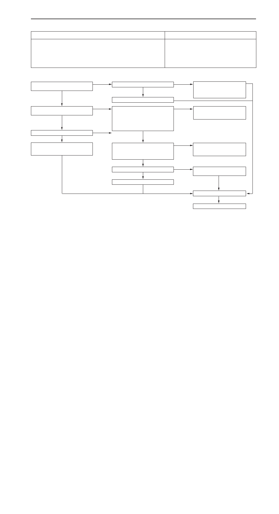
INSPECTION PROCEDURE 10

Large shocks

Probable cause

Shocks accompany shifting from N

D, N

R and during each upshift and downshift.

D

Malfunction of direct clutch

D

Malfunction of brake No. 3

D

Malfunction of stop lamp switch

D

Malfunction of inhibitor switch

D

Malfunction of forward clutch

D

Malfunction of valve body

D

Malfunction of A/T-ECU

L

: Refer to the Transmission Workshop Manual.

Is there a large shock when shifting
from N

R?

Yes

Check the time lag (within 2 seconds).

NG

Check the direct clutch clear-
ance. 

L

Check the brake No. 3 clearance.

L

No

OK

Check each accumulator. 

L

Is there a large shock when shifting
from N

D?

Yes

MUT-

II

 SERVICE DATA

D

28 – Stop lamp switch
OK: ON when brake pedal is de-

pressed
OFF when brake pedal is re-
leased

NG

Inspection Procedure 16 – Stop
lamp switch system (Refer to P.
23-26.)

No

OK

Check the kickdown cable.

NG

Repair

OK

Check each modulator valve. 

L

Check each check ball. 

L

Check each accumulator. 

L

MUT-

II

 SERVICE DATA

D

37 – Inhibitor switch
OK: MUT-

II

 display and selector

lever position should match.

NG

Inspection Procedure 14 – Inhibi-
tor switch system (Refer to P.
23-25.)

OK

Check the time lag (within 2 seconds)

NG

Check the forward clutch clear-
ance. 

L

OK

Check each accumulator. 

L

Check the trouble symptoms.

NG

Replace the A/T-ECU.

AUTOMATIC TRANSMISSION – 

Troubleshooting <A/T>

23-23

INSPECTION PROCEDURE 11

Slippage (vibration)

Probable cause

Occurs when a clutch or brake does not fully engage due to low hydraulic pressure
or a worn facing. Appears as vibration when the problem is slight.

D

Malfunction of torque converter

D

Malfunction of direct clutch

D

Malfunction of forward clutch

D

Malfunction of one-way clutch No. 1, No. 2

D

Malfunction of overdrive brake

D

Malfunction of brake No. 1, No. 2, No. 3

D

Malfunction of overdrive one-way clutch

D

Malfunction of A/T-ECU

L

: Refer to the Transmission Workshop Manual.

Does slippage occur both when moving
forward and reversing?

Yes

Check the torque converter.

NG

Replace the torque converter. 

L

No

OK

Check the overdrive clutch system. 

L

Check the overdrive one-way clutch
system. 

L

Does slippage occur in R range?

Yes

Check slippage in 3rd gear in D range.

NG

Check the direct clutch system.

L

No

OK

Check the brake No. 3 system. 

L

Does slippage occur in 1st gear?

Yes

Check for slippage in L range.

NG

Check the forward clutch system.

L

No

OK

Check the one-way clutch No. 2 sys-
tem. 

L

Does slippage occur in 2nd gear?

Yes

Check for slippage in 2nd gear in 2
range.

NG

Check the brake No. 2 system.

L

No

OK

Check the brake No. 2 system. 

L

Check one-way clutch No. 1. 

L

Does slippage occur in 3rd gear?

Yes

Check the direct clutch system. 

L

No

Check the overdrive brake system. 

L

Check the trouble symptoms.

NG

Replace the A/T-ECU.

AUTOMATIC TRANSMISSION – 

Troubleshooting <A/T>

23-24

INSPECTION PROCEDURE 12

Lockup abnormality

Probable cause

When lockup does not operate even though in the lockup range, and also when
lockup is operating and the engine is idling but then stalls.

D

Malfunction of torque converter

D

Malfunction of valve body

D

Malfunction of A/T-ECU

L

: Refer to the Transmission Workshop Manual.

Is a normal diagnosis code output?

No

To Inspection Chart For Diagnosis
Code (Refer to P. 23-9.)

Yes

Check the solenoid valve No. 3.

NG

Replace the solenoid valve No. 3. 

L

OK

Check the lockup control valve.

NG

Replace the lockup control valve. 

L

OK

Replace the torque converter. 

L

Check the trouble symptoms.

NG

Replace the A/T-ECU.

INSPECTION PROCEDURE 13

Abnormal engine braking

Probable cause

Engine braking effectiveness is poor after downshifting has occurred.

D

Malfunction of overdrive clutch

D

Malfunction of brake No. 1, No. 3

D

Malfunction of valve body

D

Malfunction of A/T-ECU

L

: Refer to the Transmission Workshop Manual.

Poor braking in 1st, 2nd and 3rd gears

Yes

Check the overdrive clutch system. 

L

No

Poor braking in 1st gear

Yes

Check the slippage in R range

OK

Malfunction of low modulator valve. 

L

No

NG

Check the brake No. 1 system. 

L

Check the brake No. 3 system. 

L

Check the trouble symptoms.

NG

Replace the A/T-ECU.

AUTOMATIC TRANSMISSION – 

Troubleshooting <A/T>

AUTOMATIC TRANSMISSION – 

Troubleshooting <A/T>

23-25

INSPECTION PROCEDURE 14

Inhibitor switch system

Probable cause

If the engine does not start in P or N range, the cause is probably a problem in
the inhibitor switch system.

D

Malfunction of inhibitor switch

D

Malfunction of harness or connector

D

Malfunction of A/T-ECU

MUT-

II

 SERVICE DATA

D

37 – Inhibitor switch
OK: MUT-

II

 display and selector

lever position should match

OK

Completed

NG

Check the inhibitor switch. (Refer to
P.23-37.)

NG

Replace

OK

Measure at inhibitor switch connector
B-04.

D

Disconnect the connector and
measure at the harness side.

D

Voltage between terminal 1 and
earth (Ignition switch: ON)
OK: System voltage

NG

Check the ignition switch. (Refer to
GROUP 54 – Ignition Switch.)

OK

Check the following connectors:
B-04, D-04

NG

Repair

OK

Check the trouble symptoms.

Check the harness wire between the
inhibitor switch and the A/T-ECU.

NG

Repair

OK

Replace the A/T-ECU.

NG

INSPECTION PROCEDURE 15

Overdrive switch system

Probable cause

If downshifting does not occur when overdrive switch is turned off while driving
in 4th gear, or if shifting to 4th gear is not possible, the cause is probably a problem
in the overdrive switch system.

D

Malfunction of overdrive switch

D

Malfunction of harness or connector

D

Malfunction of A/T-ECU

D

Malfunction of ignition switch

MUT-

II

 SERVICE DATA

D

35 – Overdrive switch
OK: MUT-

II

 display and overdrive

switch OD/OD-OFF position
should match.

OK

Completed

NG

Check the overdrive switch. (Refer to
P.23-51.)

NG

Replace

OK

Measure at overdrive switch connector
D-35.

D

Disconnect the connector and
measure at the harness side

D

Voltage between terminal 3 and
earth (Ignition switch: ON)
OK: System voltage

OK

Check the following connectors:
D-35, D-34, D-04

NG

Repair

OK

Check the trouble symptoms.

NG

Check the harness wire between the
overdrive switch and the A/T-ECU.

OK

Repair

NG

Check the ignition switch. (Refer to
GROUP 54 – Ignition Switch.)

Replace the A/T-ECU.


Content   ..  176  177  178  179   ..