Mitsubishi Pajero Pinin. Manual - part 164


  Index      Mitsubishi     Mitsubishi Pajero Pinin - service repair manual 2001 year


Search            


Content   ..  162  163  164  165   ..


Mitsubishi Pajero Pinin. Manual - part 164


ENGINE AND EMISSION CONTROL – 

Engine Control System

ENGINE AND EMISSION CONTROL – 

Engine Control System

17-3

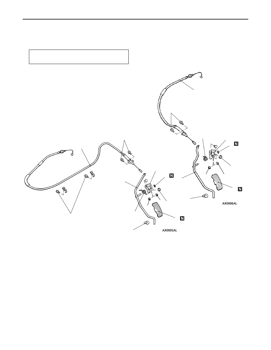
ACCELERATOR CABLE AND PEDAL

REMOVAL AND INSTALLATION

<4G9-MPI>

Post-installation Operation
Accelerator Cable Adjustment (Refer to P.17-2.)

1

2

3

2

4

<L.H. drive vehicles>

<R.H. drive vehicles>

8

6

5

7

5

3

4

6

7

8

1

5.0 

±

1.0

  N

·

m

6

6

4

5.0 

±

1.0

 N

·

m

5.0 

±

1.0

 N

·

m

12 

±

2

 N

·

m

12 

±

2

  N

·

m

Removal steps

1. Accelerator cable
2. Push-on spring nut
3. Accelerator arm assembly
4. Spring

5. Accelerator pedal bracket
6. Bushing
7. Pedal pad

"

A

A

8. Accelerator pedal stopper

INSTALLATION SERVICE POINT

A

A

"

ACCELERATOR PEDAL STOPPER INSTALLATION

Heat up the claw of the accelerator pedal pad with a drier
and etc. before installation.
NOTE
Apply some soapsuds to the claw to facilitate installation if
there is any difficulty.

ENGINE AND EMISSION CONTROL – 

Emission Control System <MPI>

17-4

EMISSION CONTROL SYSTEM <MPI>

GENERAL

OUTLINE OF CHANGES

The following contents have been established to correspond to the addition of vehicles with 4G9-MPI
engine. The other contents are the same as before.

GENERAL INFORMATION

The emission control system consists of the following subsystems:

D

Crankcase emission control system

D

Evaporative emission control system

D

Exhaust emission control system

Items

Name

Specification

Crankcase emission
control system

Positive crankcase ventilation (PCV) valve

Variable flow type
(Purpose: HC reduction)

Evaporative emission
control system

Canister
Purge control solenoid valve

Equipped
Duty cycle type solenoid valve
(Purpose: HC reduction)

Exhaust emission
control system

Air-fuel ratio control device –  MPI system

Oxygen sensor feedback type
(Purpose: CO, HC, NOx reduction)

Exhaust gas recirculation system

D

EGR valve

D

EGR control solenoid valve

Equipped
Single type
Duty cycle type solenoid valve
(Purpose: NOx reduction)

Catalytic converter

Monolith type
(Purpose: CO, HC, NOx reduction)

EMISSION CONTROL DEVICE REFERENCE TABLE

Related parts

Crankcase
emission
control 
system

Evaporative
emission
control 
system

Air/fuel 
ratio 
control 
system

Catalytic
converter

Exhaust
gas 
recircula-
tion system

Reference
page

PCV valve

×

17-9*

Purge control solenoid valve

×

17-9

MPI system component

×

×

GROUP 13B

Catalytic converter

×

17-14

EGR valve

×

17-12

EGR control solenoid valve

×

17-13

NOTE
*: Refer to the ’00 PAJERO PININ Workshop Manual (Pub. No. CKRE00E1)

ENGINE AND EMISSION CONTROL – 

Emission Control System <MPI>

17-5

SERVICE SPECIFICATIONS

Items

Standard value

Purge control solenoid valve coil resistance (at 20

_

C)   

36 –  44

EGR control solenoid valve coil resistance (at 20

_

C)   

36 –  44

VACUUM HOSE

VACUUM HOSE PIPING DIAGRAM

PCV valve

OFF

EGR valve

Air cleaner

ON

Canister

Purge control
solenoid valve

EGR control
solenoid valve

Oxygen sensor
<rear>

Air

OFF

ON

Oxygen sensor
<front>

M E

A

ENGINE AND EMISSION CONTROL – 

Emission Control System <MPI>

17-6

VACUUM CIRCUIT DIAGRAM

From air
cleaner

Intake manifold

Throttle body

To 
combustion
chamber

Fuel
pressure
regulator

EGR control 
solenoid valve
(ON: OPEN)

Canister

Purge control 
solenoid
valve
(ON: OPEN)

EGR valve

Vacuum hose colour
B:

Black

G: Green
L:

Light blue

R: Red
Y:

Yellow

M

P

A

L

G

Y

G

G

R

B

VACUUM HOSE CHECK

1.

Using the piping diagram as a guide, check to be sure
that the vacuum hoses are correctly connected.

2.

Check the connection condition of the vacuum hoses,
(removed, loose, etc.) and check to be sure that there
are no bends or damage.

VACUUM HOSE INSTALLATION

1.

When connecting the vacuum hoses, they should be
securely inserted onto the nipples.

2.

Connect the hoses correctly, using the vacuum hose piping
diagram as a guide.


Content   ..  162  163  164  165   ..