Mitsubishi Pajero Pinin. Manual - part 160


  Index      Mitsubishi     Mitsubishi Pajero Pinin - service repair manual 2001 year


Search            


Content   ..  158  159  160  161   ..


Mitsubishi Pajero Pinin. Manual - part 160


ENGINE AND EMISSION CONTROL – 

Emission Control System

17-9

POSITIVE CRANKCASE VENTILATION SYSTEM
CHECK

1.

Remove the ventilation hose from the PCV valve.

2.

Remove the PCV valve from the rocker cover.

3.

Reinstall the PCV valve at the ventilation hose.

4.

Start the engine and run at idle.

5.

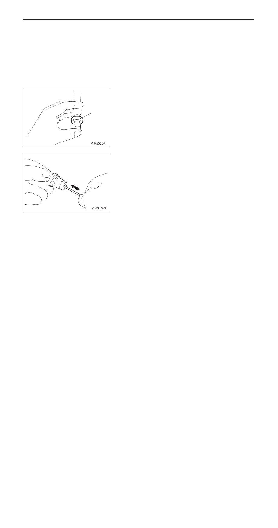
Place a finger at the opening of the PCV valve and check
that vacuum of the intake manifold is felt.

NOTE
At this moment, the plunger in the PCV valve moves back
and forth.

6.

If vacuum is not felt, clean the PCV valve or replace it.

PCV VALVE CHECK

1.

Insert a thin rod into the PCV valve from the side shown
in the illustration (rocker cover installation side), and move
the rod back and forth to check that the plunger moves.

2.

If the plunger does not move, there is clogging in the
PCV valve. In this case, clean or replace the PCV valve.

PCV valve

ENGINE AND EMISSION CONTROL – 

Emission Control System

Purge control solenoid valve

Purge control 
solenoid valve

17-10

EVAPORATIVE EMISSION CONTROL SYSTEM

GENERAL INFORMATION

The evaporative emission control system prevents
fuel vapours generated in the fuel tank from escaping
into the atmosphere.
Fuel vapours from the fuel tank flow through the
fuel tank pressure control valve and vapour
pipe/hose to be stored temporarily in the canister.
When driving the vehicle, fuel vapours stored in
the canister flow through the purge solenoid and
purge port and go into the intake manifold to be

sent to the combustion chamber.
When the engine coolant temperature is low or when
the intake air quantity is small (when the engine
is at idle, for example), the engine control unit turns
the purge solenoid off to shut off the fuel vapour
flow to the intake manifold.
This does not only insure the driveability when the
engine is cold or running under low load but also
stabilize the emission level.

SYSTEM DIAGRAM

From fuel tank

Canister

Purge control 
solenoid valve
(ON: Open)

Air flow sensor

Barometric pressure
sensor

Control
relay

Throttle body

Engine-ECU

Engine coolant 
temperature sensor

Intake air 
temperature sensor

Battery

COMPONENT LOCATION

ENGINE AND EMISSION CONTROL – 

Emission Control System

17-11

PURGE CONTROL SYSTEM CHECK

1.

Disconnect the vacuum hose (red stripe) from the throttle
body and connect it to a hand vacuum pump.

2.

Plug the nipple from which the vacuum hose was removed.

3.

When the engine is cold or hot, apply a vacuum of 53
kPa, and check the condition of the vacuum.

When engine is cold
(Engine coolant temperature: 40

_

C or less)

Engine condition

Normal condition

At idle

Vacuum is maintained

3,000 r/min

When engine is hot
(Engine coolant temperature: 80

_

C or higher)

Engine condition

Normal condition

At idle

Vacuum is maintained

3,000 r/min (fore
approximately 3 minutes
after the engine is started.)

Vacuum will leak.

PURGE PORT VACUUM CHECK

1.

Disconnect the vacuum hose (red stripe) from the throttle
body purge vacuum nipple and connect a hand vacuum
pump to the nipple.

2.

Start the engine.

3.

Check that vacuum is produced almost constantly
regardless of engine revolution.

4.

When the vacuum is not produced, clean the hose as
it may be clogged.

Plug

Vacuum hose
(red stripe)

Vacuum hose
(red stripe)

Vacuum

Engine speed (r/min)

ENGINE AND EMISSION CONTROL – 

Emission Control System

17-12

PURGE CONTROL SOLENOID VALVE CHECK

NOTE
When disconnecting the vacuum hose, always make a mark
so that it can be reconnected at original position.
1.

Disconnect the vacuum hose (black stripe, red stripe) from
the solenoid valve.

2.

Disconnect the harness connector.

3.

Connect a hand vacuum pump to nipple (A) of the solenoid
valve (refer to the illustration at left).

4.

Check airtightness by applying a vacuum with voltage
applied directly from the battery to the purge control
solenoid valve and without applying voltage.

Jumper wire

Nipple B

Normal condition

Connected

Open

Vacuum leaks

Closed

Vacuum maintained

Disconnected

Open

Vacuum maintained

5.

Measure the resistance between the terminals of the
solenoid valve.

Standard value: 36 – 44 

 (at 20

_

C)

Battery

B

A


Content   ..  158  159  160  161   ..